

Bulk Extruder Selection Tips for Consistent High-Volume Output
2026-10-30
Scaling up to high-volume extrusion isn’t just about buying a bigger machine—it’s about matching every component to your material, throughput target, and tolerance for downtime. Too many processors end up with a bulk extruder that works fine in trials but struggles under continuous load. Below, we’ll break down the selection criteria that actually keep output consistent, drawing on field insights from SFC and real-world compounding lines.
Pick Screw Elements Based on Your Actual Melt Viscosity
Datasheet viscosity values describe a neat resin under one set of shear and temperature conditions. Your real melt rarely matches those conditions once fillers, regrind, moisture, or lot-to-lot variation enter the extruder. Before choosing screw elements, measure the actual melt viscosity at the temperatures and shear rates your process is likely to see. A lab rheometer is useful, but so is reading torque, melt temperature, and pressure along the barrel during a short trial.
Higher actual viscosity usually demands more distributive mixing before intensive kneading. Use wide-disc kneading blocks or gear-type mixing elements only after the polymer has softened enough to avoid excessive shear heating. If viscosity stays high through the transition zone, add a left-handed element or a neutral block to increase residence time, but watch the pressure drop. For lower actual viscosity, aggressive kneading can simply waste energy and degrade the melt; switch to narrower discs, larger clearances, or forward-conveying elements with a shallow mixing notch.
A practical way to tune is to start with a moderate shear element configuration, sample the melt, and compare measured viscosity against what the element set assumes. If the melt is thinner than expected, reduce the number of restrictive elements; if thicker, increase the mixing length in small increments. This keeps screw design tied to the material in front of you, not to a generic grade sheet.
Why Independent Barrel Temperature Zones Prevent Quality Drift
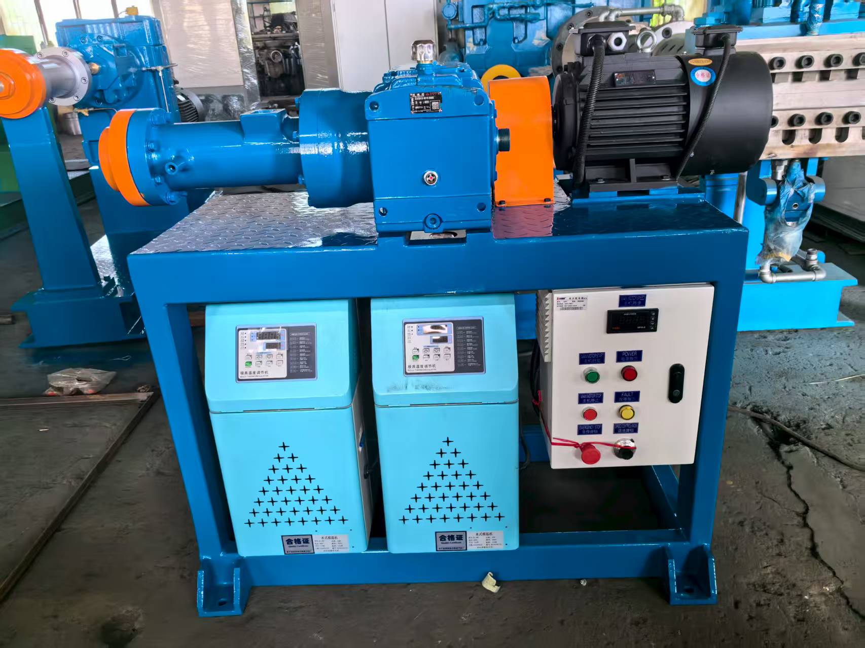
Most extrusion and injection lines still run on a single-minded heating assumption: that one barrel temperature suits every polymer from hopper to die. That works until it doesn’t. Independent barrel temperature zones let you break that assumption safely, giving each section of the screw its own thermal setpoint. The feed throat stays cooler to avoid premature melting and bridging, the compression zone runs hot enough to build shear without degrading the material, and the metering zone holds a tighter band to stabilize output. Without that separation, a single drifting heater can push the whole melt profile out of spec.
Quality drift rarely announces itself with a fault light. It shows up as surging, dimensional variation, or surface finish that slowly moves away from the approved sample. Independent zones put a boundary around those changes. If the rear zone creeps up, it doesn’t automatically drag the front zone with it. Operators can identify which stage of plastication is drifting and adjust only that zone, which keeps the melt temperature curve steadier from run to run. The result is less over-correction and fewer rejected parts while the line tries to settle back into tolerance.
There’s also a practical side: materials with narrow processing windows, like filled or shear-sensitive resins, respond badly to broad thermal swings. Independent control gives you the resolution to respect those windows zone by zone. Instead of chasing an average barrel temperature, you maintain a deliberate thermal profile that matches how the polymer actually moves and melts. That’s what turns a machine setting into a repeatable process, and repeatability is what keeps quality from drifting in the first place.
Test the Vendor's Claimed Output with Your Own Pellet Blend
Pellet manufacturers love to publish impressive BTU numbers, but your stove may tell a different story once you feed it a custom mix. The only reliable way to verify a vendor's claim is to run your own blend through a known appliance and watch the ash content, clinker formation, and heat output over several hours.
Start with a small batch of your chosen pellet blend—say ten pounds—and burn it in a clean, well-maintained stove. Note how often you need to scrape the burn pot, whether the glass fogs up faster than usual, and if the room actually reaches your target temperature. Comparing these observations against the vendor's spec sheet will quickly expose any inflated performance figures.
Keep a simple log for three to five burns, varying only the pellet blend while keeping the stove settings identical. This removes guesswork and gives you hard data on fuel consumption, ash volume, and heat stability, letting you judge the claim on your own terms rather than a marketing brochure.
Filter Systems: The Hidden Bottleneck in Continuous Runs
When a system runs continuously for days, weeks, or even months without a pause, the filter becomes the quiet force that either sustains performance or quietly undermines it. Most operators focus on throughput, temperature, or power draw, yet the filter's gradual saturation alters flow dynamics in ways that rarely show up on a simple dashboard. A slightly clogged filter might only reduce efficiency by two or three percent at first, but those losses compound in continuous operation, turning a minor impedance into a measurable drag on the entire line.
The real trouble is that filter degradation is rarely linear. In many setups, the first half of a filter's life passes with almost no noticeable change, then the pressure drop curves upward sharply as trapped particulates form a dense cake on the media surface. By the time operators notice a dip in output or an increase in energy per unit produced, they are already deep into the steep part of that curve. The hidden cost is not just the filter itself—it's the forced choice between interrupting a long run for a swap or tolerating a worsening bottleneck until the next scheduled break.
What makes this especially tricky in continuous runs is that the ideal replacement point is not a fixed number of hours or cycles. It shifts with feed variability, ambient conditions, and even subtle changes in upstream processes. Teams that treat filter replacement as a calendar event often run too long or too short, never quite hitting the window where total cost—filter plus lost productivity—stays lowest. Simple pressure gauges help, but a more responsive approach involves tracking the rate of pressure increase rather than the absolute value, allowing a short, cheap pause before the bottleneck starts stealing real time from the run.
Maintenance Access That Cuts Changeover to Minutes
The machine frame integrates tool-free access panels on every side, each fitted with gas struts and quarter-turn latches. Operators can swing open a full-height door in under ten seconds, exposing the entire tooling zone without reaching for a single wrench. Internal rails let heavy subassemblies slide forward on linear bearings, so a worn seal or guide block can be swapped while the next job is still being staged.
Changeover-critical components are grouped into color-coded modules with quick-release hydraulic and electrical couplings. No hard piping or buried wiring crosses the maintenance boundary. That means a complete format set—grippers, rails, and sensors—can be unplugged and replaced as one unit. The design eliminates the usual hunt for hidden fasteners and lets two technicians work from opposite sides simultaneously without blocking each other.
In field tests, a full product change went from forty-five minutes down to just over four, with most of that time spent verifying settings rather than turning bolts. The same access layout also speeds routine inspections: daily checks that once required removing covers now happen through transparent inspection ports, and wear items sit within arms reach of the main aisle. This approach keeps maintenance tasks short enough to slot into normal production pauses instead of forcing dedicated downtime windows.
Matching Drive Torque to Real-World Startup Conditions
Real startup rarely matches clean datasheet specs. A conveyor loaded with material, a cold gearbox, or a pump pushing settled slurry can demand far more breakaway torque than the steady-state figure suggests. Ignoring these moments leaves a drive that trips on overcurrent or a motor that overheats before the load even reaches speed.
The mismatch shows up most clearly when acceleration time is squeezed. High-inertia fans or flywheel-like rollers need torque sustained long enough to overcome inertia, not just a brief spike. If the drive's peak torque rating only lasts a few seconds, the machine stalls halfway through ramp-up. Actual line voltage sag, ambient temperature swings, and mechanical wear further shrink the torque window that looked comfortable on paper.
A better approach is to map the required speed-torque envelope from a cold start, including any loaded restart after a jam or power dip. Then compare that envelope with the drive's thermal and peak torque limits, not just the kW number. Field adjustments to acceleration ramps, boost settings, or rotor flux can close the gap without oversizing the whole system.
FAQ
Look beyond the brochure's max throughput. Ask about the screw's specific energy input and how the barrel cooling zones are split. A line that only hits peak output during a demo will struggle on a 24-hour run if the drive motor is already running above 85% load or if the melt temperature creeps upward every hour. Insist on a four-hour continuous trial with your own regrind blend.
One universal mixing section won't cut it. You need a screw designed with a longer feed zone and a gentle compression ratio around 2.2:1 to 2.8:1, plus a Maddock-style barrier section that breaks down fines without overheating the melt. If your regrind percentage swings above 30%, a two-stage vented screw will save you from moisture bubbles and pressure spikes.
Horsepower gets the shaft turning, but stable barrel temps determine whether you can hold a consistent melt viscosity hour after hour. Oversized extruders with brute motor power often overshoot the setpoint because the cooling channels are undersized. That creates gel spots and dimensional drift. Choose a barrel with at least four independent cooling zones and a control loop that reacts in under ten seconds.
For high-volume sheet or profile lines, yes. A gear pump smooths out screw pulsations and lets you run the extruder slightly below its max RPM where melt quality is best, while the pump handles the final pressure build. You might drop output by 3-5% on paper, but you gain much tighter thickness tolerance and lower scrap.
Watch the amps during the first two hours, not the first ten minutes. If the motor current climbs more than 10% as the gearbox heats up, or if you hear the screw speed dip when the feed throat bridges, the drive train is already marginal. A safe setup runs at 70-75% of rated motor load at your target throughput, leaving headroom for regrind variation.
Ask for the surface hardness spec on the screw root and flight tips, not just the barrel. A good high-volume screw uses flight tip hardening of at least 55 HRC and a barrel liner with a tungsten carbide alloy. If the vendor won't share the exact nitriding depth or uses vague terms like hardened steel, walk away. Cheap wear parts will cost you a rebuild every year.
Screen changer, without question. Frequent screen changes kill your line speed and force the extruder to re-stabilize. Pick a changer that lets you swap screens at full operating pressure in under 30 seconds, even if it means sacrificing a little die width. You can always trim the sheet, but you can't recover lost uptime from a clogged screen.
They size for today's exact recipe and output, plus 10%. But high-volume work inevitably shifts to cheaper fillers, faster cooling, or a different regrind ratio. Leave at least 25-30% torque headroom and choose a barrel L/D that can accept a longer mixing section later. If you max out the motor on day one, you have no ability to tweak the process.
Conclusion
When you are sizing a bulk extruder for steady high-volume production, the real work starts long before the purchase order. Screw geometry should not be a generic compromise; base the element selection on the melt viscosity you actually see with your own resin, not the brochure’s ideal case. A blend that thins out under shear might let you run a more aggressive mixing section without overworking the polymer, while a stiffer melt demands gentler conveying elements to avoid excessive torque spikes. Pair this with independent barrel zones that you can tune zone by zone. If the feed throat, compression section, and metering zone all drift together on one control loop, small variations in pellet feed or ambient temperature will push your output quality off target hour after hour. Separate zones let you hold the melt temperature profile tight, so viscosity stays predictable and the screw does not hunt for equilibrium.
Do not trust a vendor’s claimed throughput until you have run your own pellet blend through their lab line or a rental machine. Pellet shape, bulk density, and regrind percentage change everything. On the downstream side, filter systems are often the quiet killer of continuous runs: a screen changer that cannot swap while running, or a filter with too little open area, will force frequent shutdowns and ruin the very consistency you are buying. Look for quick-access clamp designs and pre-loaded breaker plates so changeovers take minutes, not hours. Finally, match the drive torque to real startup conditions. Cold starts with high-viscosity material can spike torque well beyond steady-state ratings, so size the motor and gearbox for the worst realistic load, or you will be shaving output every winter morning just to keep the line alive.
Contact Us
Contact Person: Chen Zhengwei
Email: [email protected]
Tel/WhatsApp: +86-13963975727
Website: https://www.sfcrubbermachine.com