

OEM EMI Filter Solutions for Reliable Electronic Design
2026-10-12
Electromagnetic interference rarely announces itself—it shows up as sporadic sensor noise, a flickering display, or a failed emissions test at the worst possible moment. For OEM engineers, these aren't minor annoyances; they're production delays and reputational risks. Reliable electronic design demands EMI filtering that matches the real operating environment, not a generic datasheet curve. That's where DOREXS comes in, with OEM-focused filter solutions engineered to keep your circuits quiet and your compliance schedules on track.
Conducted Noise Starts Somewhere—Find the Real Source
Chasing conducted noise on a power rail often feels like playing whack-a-mole. You add a ferrite bead here, a capacitor there, and the emission peak just shifts to a different frequency or moves to another cable. The real problem is rarely where you first measure it. Noise appears at the point of least resistance, not necessarily at the point of origin. If you keep treating the symptom, you’ll never run out of symptoms.
The actual source can hide in plain sight: a switching regulator with an aggressive edge rate, a motor driver dumping reverse recovery current, or even a seemingly innocent microcontroller toggling I/O lines in sync. Conducted noise couples through parasitic capacitance, shared ground impedance, or magnetic fields between adjacent traces. What you see on the spectrum analyzer is the superposition of multiple contributors, each with its own signature and path. Without tracing each branch back, any fix is just a guess dressed up as engineering.
Start by mapping the topology of your power distribution and return paths. Disconnect subcircuits one by one, or inject a known disturbance and watch how it propagates. A current probe clamped around individual wires or PCB traces can reveal which branch actually carries the offending energy. Once the true source is identified, a small impedance change or a targeted snubber often solves what a dozen trial-and-error filters could not. Quiet systems are built from the source outward, not from the test point backward.
Your Filter's Datasheet Curve Is Not the Whole Story
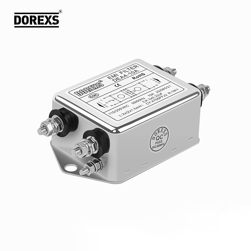
Engineers often treat the insertion loss curve on a filter datasheet as gospel, but anyone who has chased a stubborn interference problem knows that paper performance rarely survives contact with the real world. The curve is typically measured in a 50-ohm system with perfectly matched terminations, yet your actual circuit may present wildly different impedances at the filter's ports. A few stray picofarads of board capacitance, a slightly inductive ground return, or even the physical proximity of other components can shift the cutoff frequency and ripple in ways the datasheet never hints at. When the filter is operating near the edge of its specified band, those small deviations become the difference between a clean pass and a failed emissions test.
Temperature and component tolerance add another layer of unpredictability. A ceramic capacitor can lose a significant fraction of its capacitance as it warms up, dragging a notch filter's center frequency off target. Inductors with ferrite cores exhibit nonlinear behavior when current approaches saturation, distorting the very shape of the response curve. If you design a filter assuming ideal values and room-temperature specifications, a product that works on the bench may fail in a hot enclosure or after a few months of aging. Smart designers build in margin, test with real source and load impedances, and verify performance across the full operating range before trusting a datasheet plot.
The real story is that a filter's performance emerges from a system, not from a standalone component. A curve printed on paper is a snapshot under controlled conditions; your printed circuit board, connectors, and surrounding circuitry all contribute their own parasitic elements. To avoid surprises, measure the filter in situ, use impedance-matched layouts, and consider Monte Carlo simulations that account for part tolerances. Only then will the filter behave as intended, rather than as the datasheet might have led you to believe.
High-Density OEM Boards Don't Tolerate Generic Filters
OEM boards packed with tightly spaced components and high-speed signal traces leave little room for error. A one-size-fits-all filter might look fine on paper, but once it meets the real current draw and thermal load of a dense board, performance falls apart. You see it in the voltage ripple creeping up, the occasional brownout under load, or that subtle interference that only shows up during extended operation. Generic parts simply weren't tuned for the specific impedance and switching frequencies these boards demand.
The physical fit matters just as much as the electrical behavior. Many off-the-shelf filters come in bulky footprints that crowd adjacent components or block airflow in enclosures that are already starved for space. Even when a generic unit fits mechanically, its lead spacing or mounting style can force awkward routing and degrade signal integrity. Designers who have spent weeks optimizing a layout don't want to compromise it for a filter that was never meant to share the board.
What works instead is a filter chosen or custom-tuned around the actual load profile, switching frequency, and thermal environment of the specific OEM design. It might mean a slightly higher unit cost, but it eliminates the debugging cycles, field failures, and last-minute layout changes that generic filters so often trigger. On a dense board, every component has to earn its place, and a filter that ignores the board's unique constraints rarely does.
Cutting Common-Mode Current Without Losing Signal Edges
Designers often treat common-mode current as an unavoidable side effect of high-speed signaling, but its consequences ripple far beyond EMC test failures. The challenge lies in suppressing this current without rounding off the very edges that carry timing information. A blunt approach like adding excessive ferrite beads or a poorly chosen choke can introduce differential-mode impedance that slows transitions, creating eye closure and bit errors. The key is to recognize that common-mode and differential-mode currents travel different paths, and any suppression element must distinguish sharply between the two.
Practical solutions start with selecting a common-mode choke whose leakage inductance remains negligible at the frequencies of interest. A well-wound toroid with bifilar or sectional windings can present high impedance to common-mode noise while appearing nearly transparent to the differential signal. For board-level designs, routing differential pairs tightly together and placing a common-mode filter right at the connector or cable entry point minimizes the antenna area without adding extra vias or stubs that degrade edges. In systems with isolated grounds, a low-capacitance digital isolator or transformer can block common-mode paths entirely, provided its coupling capacitance is kept in the sub-picofarad range.
Verification must go beyond a simple spectrum analyzer check. Use a fast differential probe and an oscilloscope with at least five times the bandwidth of the signal to compare rise times before and after the filter. If the edge has slowed by more than a few percent, the suppression network needs rework. Time-domain reflectometry can also reveal hidden impedance discontinuities introduced by the filter. A well-executed design keeps common-mode emissions below the limit while preserving edge rates within the receiver's timing budget, often with no measurable penalty to the signal.
What Happens When Temperature and Vibration Meet EMI Components
EMI components don't live in a static world. A ferrite bead that works beautifully at room temperature can lose a noticeable chunk of its impedance once the board heats up, because the ferrite material's permeability shifts with temperature. At the same time, engine vibration or fan rotation can physically shake the component, making its lead wires flex and its solder joints work-harden. What started as a stable filter becomes something closer to a moving target.
Vibration hits ceramic capacitors and magnetic cores in different but equally annoying ways. MLCCs can act like tiny piezoelectric speakers, turning mechanical energy into electrical noise that rides on the supply rail. Ferrite cores, being brittle, can develop micro-cracks under sustained vibration, which reduces their effective cross-section and lowers inductance—sometimes quietly, sometimes with an audible whine when the switching frequency aligns with a mechanical resonance.
The real trouble begins when temperature cycling and vibration team up. Different materials expand and contract at different rates, so a solder joint that survives a thermal soak may start to fatigue once vibration adds cyclic stress to the same spot. Over time, cracks propagate, contact resistance climbs, and an EMI filter that once kept emissions within spec can drift out of compliance without any obvious failure. Designers who treat temperature and vibration as separate problems often miss this combined wear-out mode.
Real Load Testing Separates Reliable Filters from Lab Queens
Bench numbers tell a cozy story. A filter can breeze through a 24-hour static efficiency run and still fall flat when a production line pushes twice the rated flow through it. That gap between spec-sheet confidence and real-world collapse is where lab queens get exposed.
Real load testing doesn't just crank up the pressure for an hour. It cycles filters through surge conditions, temperature swings, and particle loads that mimic actual plant air or fluid. Filters that hold their pressure drop steady and keep capturing fines under those conditions are the ones worth putting in front of a customer.
The difference shows up in maintenance logs. A filter that only performs in clean, controlled lab air will clog early, spike energy draw, or let fines slip past once the system gets dirty. A reliable filter keeps its removal efficiency and flow curve predictable even when the load is ugly. That's the only kind of performance that matters outside a test lab.
FAQ
A purpose-built OEM filter is matched to the actual impedance characteristics of the load and source, not just a generic 50-ohm assumption. It accounts for specific switching frequencies, dv/dt edges, and layout parasitics. Off-the-shelf filters often target broad ranges, which can leave narrowband emissions under-attenuated or add unnecessary bulk and cost.
Rated voltage, continuous current, and leakage current are basic. The more critical ones are insertion loss curves under real source and load impedances, saturation behavior of common-mode chokes, X and Y capacitor values versus touch current limits, and the filter's resonance points. Neglect these and you may pass a test bench but fail in the field.
Placement is as important as the filter topology. The filter should sit at the boundary of the shielded enclosure, with input and output leads separated. Any coupling across the filter, from unfiltered lines running parallel to filtered ones, bypasses the attenuation and sends noise directly into the system. Short, low-inductance ground connections are vital.
Directly, it addresses conducted emissions on cables. But because cables act as antennas, reducing conducted noise can lower radiated emissions too. However, if there is significant common-mode current on internal harnesses or PCB traces, a filter at the power entry alone won't fix poor internal layout.
Inrush current and dv/dt stress. High-frequency PWM edges can cause repeated voltage spikes across filter capacitors, leading to premature wear. Also, the saturation of common-mode chokes under load imbalance is frequently ignored. A robust design derates for temperature rise and uses pulse-rated capacitors.
Measure the actual noise spectrum with a line impedance stabilization network in the intended end product, not on a bare bench. Then choose filter stages that target only the troublesome frequency bands. Oversizing adds cost, weight, and can even introduce new resonances that worsen performance at other frequencies.
Enclosure material, mounting method, and cable routing all influence filter behavior. A filter mounted on a painted or non-conductive surface loses its chassis ground reference. Metallic standoffs, conductive gaskets, and keeping the filter away from high-current switching nodes help maintain predictable attenuation.
Thermal cycling, humidity, and voltage transients age capacitors. Ferrite cores can crack from vibration. Also, the production unit may differ from the prototype due to component substitutions. To prevent this, specify temperature ratings, vibration resistance, and conduct accelerated life tests on the actual production filter.
Conclusion
Finding the actual source of conducted noise is where reliable OEM EMI filtering begins. It is rarely where the schematic suggests, and assuming the filter's datasheet curve tells the full story is a mistake—those curves are measured under ideal bench conditions that never survive contact with a densely packed OEM board. High-density designs leave no room for one-size-fits-all filters, and the parasitic coupling between tightly routed traces can easily defeat a component that looks perfect on paper. Effective solutions have to be shaped around the board's real geometry, not just the nominal attenuation specs.
The harder challenge is suppressing common-mode current without rounding off the fast signal edges your design depends on. That demands filters with carefully controlled impedance and layout, not brute-force capacitance. Then there are the environmental realities: temperature swings and vibration loosen connections, shift ferrite properties, and crack solder joints, so the filter that passes on a static bench can fail in the field. Real load testing—pushing the filter with the actual switching waveforms, thermal cycles, and mechanical stress it will face—is what separates components that merely measure well from ones that hold up over the product's life. Reliable electronic design isn't about the quietest filter in isolation; it's about the one that stays quiet where it actually lives.
Contact Us
Contact Person: Eric
Email: [email protected]
Tel/WhatsApp: 8618117837140
Website: https://www.emcdorexs.com