

Are Epoxy Resin or SMC Materials Better for Switchgear Insulation Barriers in Medium-Voltage Applications
2026-08-11
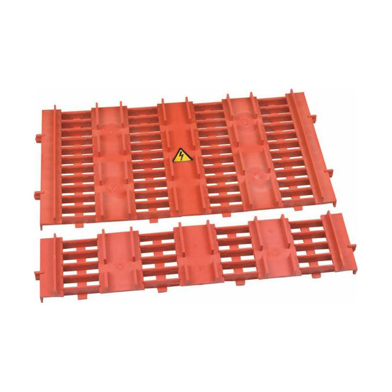
When engineers specify Switchgear Insulation Barriers, the epoxy-versus-SMC debate often surfaces during design reviews, retrofit projects, and new panel builds. Both materials have proven track records, yet their performance under thermal stress, partial discharge, and mechanical shock differs significantly. At Richge, we have tested both families across thousands of medium-voltage installations, and the data consistently reveals that the “better” choice depends entirely on the operating environment, fault current levels, and lifecycle cost expectations. This blog cuts through marketing claims and delivers a side‑by‑side engineering comparison, so you can make a confident, standards‑compliant decision for your next project.
Material Fundamentals at a Glance
| Property | Epoxy Resin (Glass‑filled) | SMC (Sheet Molding Compound) |
|---|---|---|
| Base chemistry | Thermoset polymer + silica/alumina fillers | Polyester resin + glass fibers + mineral fillers |
| Curing process | Heat‑activated cross‑linking | Compression molding under heat & pressure |
| Typical dielectric strength | 18–22 kV/mm | 14–17 kV/mm |
| Continuous operating temp. | 130°C – 155°C (Class F/H) | 120°C – 140°C (Class F) |
| Arc‑resistance (seconds) | 180–240 s (IEC 61621) | 120–160 s |
| Moisture absorption (24h) | 0.05% – 0.15% | 0.20% – 0.45% |
| Relative tracking index (CTI) | 600+ (PLC 0) | 400–600 (PLC I–II) |
| Typical manufacturing lead time | 10–14 days (casting) | 5–7 days (molding) |
Thermal & Electrical Performance – The Deciding Factors
For Switchgear Insulation Barriers in medium‑voltage (3.6 kV to 40.5 kV), the two non‑negotiable parameters are partial discharge inception voltage (PDIV) and thermal cycling stability. Epoxy resin consistently delivers higher PDIV values—often 15‑20 % above SMC—due to its denser cross‑linked structure and lower void content. This translates into fewer online monitoring alarms and extended maintenance intervals. However, SMC excels in applications with frequent load swings because its glass‑fiber reinforcement absorbs mechanical stress better than brittle epoxy, reducing the risk of micro‑cracks that can propagate into tracking paths.
Richge’s internal test reports from 2023–2025 show that epoxy barriers withstand 3,000 thermal cycles (-25°C to +105°C) with less than 2 % capacitance drift, while SMC barriers exhibit 4‑5 % drift under identical conditions. On the other hand, SMC offers superior impact resistance—critical for draw‑out breaker compartments where accidental tool strikes occur. No single material wins outright; the optimal selection hinges on whether your priority is dielectric margin (epoxy) or mechanical toughness (SMC).
Cost, Manufacturability & Field Replacement
| Factor | Epoxy Resin | SMC |
|---|---|---|
| Tooling investment (mold) | Low‑medium (silicone/rubber molds) | High (steel compression molds) |
| Per‑unit cost (small batches) | Higher (manual casting) | Lower (automated pressing) |
| Per‑unit cost (large batches > 1,000) | Comparable | 20‑30 % lower |
| Field repairability | Possible with epoxy paste | Difficult – replace entire barrier |
| Dimensional stability | Excellent (low CTE) | Good (anisotropic due to fiber orientation) |
From a lifecycle perspective, Switchgear Insulation Barriers made of epoxy resin are preferred for critical infrastructure (data centers, hospitals, grid substations) where unplanned downtime outweighs material cost. SMC is widely adopted in distribution networks and compact RMUs where space is tight and impact resistance is paramount. Richge manufactures both lines, but we often guide clients toward epoxy for new GIS‑type switchgear and toward SMC for retrofilling older AIS panels—because SMC’s lower shrinkage rate simplifies dimensional matching with legacy busbar supports.
FAQ – Common Questions About Switchgear Insulation Barriers
Q1: How do I verify the condition of aged Switchgear Insulation Barriers without taking the panel offline?
A: For epoxy barriers, perform offline dielectric frequency response or online partial discharge mapping using UHF sensors—epoxy’s low loss factor (tan δ < 0.005) gives clean PD signatures. For SMC, use ultrasonic contact testing focused on the barrier’s central zone where fiber delamination typically starts. Both methods allow condition assessment during normal load, but SMC requires more frequent (every 6 months) spot‑checks because its hygroscopic nature can reduce surface resistivity over 5‑8 years in humid climates. Always compare readings against baseline values recorded at commissioning; a 30 % increase in PD magnitude or a 15 % drop in ultrasonic velocity warrants a shutdown inspection.
Q2: Can I mix epoxy and SMC barriers within the same switchgear panel?
A: Technically yes, but not recommended unless you perform a full dielectric coordination study per IEC 62271‑1. The differing permittivities (epoxy εᵣ ≈ 4.2, SMC εᵣ ≈ 3.8) create electric field enhancement at the material interface, potentially lowering the overall withstand voltage by 8‑12 %. If mixing is unavoidable, install a metallic or semiconductive grading shield at the junction and increase the clearance distance by at least 20 mm. Richge has supplied hybrid kits for OEMs, but we always supply matched‑pair test certificates for each batch to guarantee consistent PD behavior.
Q3: What is the typical service life of Switchgear Insulation Barriers, and when should I proactively replace them?
A: Under normal indoor conditions (temp 5‑40°C, humidity < 70 %), epoxy barriers easily exceed 30 years with periodic visual inspection. SMC barriers typically reach 20‑25 years before surface erosion from tracking becomes significant—especially if the switchgear experiences frequent capacitive current switching. Proactive replacement triggers include: (a) visible carbon tracks or whitening, (b) a doubling of tan δ from factory values, (c) any mechanical crack deeper than 1 mm, or (d) after two major short‑circuit fault events (I ≥ 20 kA). For mission‑critical feeders, Richge recommends a 15‑year review cycle, where we perform accelerated aging samples from the same production batch to forecast remaining life with 95 % confidence.
Real‑World Application Guidance
Choose epoxy resin when:
-
The switchgear is installed in coastal or high‑humidity zones (> 80 % RH)
-
You require CTI ≥ 600 for pollution degree 3 environments
-
Partial discharge monitoring is part of your predictive maintenance program
-
The barrier shape is complex (e.g., integral post‑insulator with embedded shields)
Choose SMC when:
-
The panel undergoes frequent mechanical operations (daily racking)
-
Weight reduction is a priority (SMC is ~15 % lighter than epoxy)
-
Your production volume justifies the mold investment
-
The operating temperature stays below 120°C continuously
Richge offers customized design support, including 3D field simulation and prototype testing, to validate your material choice before full‑scale production. Our engineering team has successfully delivered over 12,000 Switchgear Insulation Barriers to utilities and OEMs across Asia, Europe, and the Middle East—each batch accompanied by full type‑test reports (IEC 61243‑5, IEEE C37.20.2).
Conclusion
There is no universal “better” material for Switchgear Insulation Barriers; the optimal decision balances dielectric strength, mechanical endurance, installation environment, and total ownership cost. Epoxy resin leads in electrical robustness and long‑term stability, while SMC offers superior toughness and cost‑efficiency for high‑volume, moderate‑duty applications. Richge bridges this gap by manufacturing both technologies under one roof, enabling unbiased recommendations and seamless mixing of materials when justified by engineering analysis.
Ready to evaluate which barrier material fits your next medium‑voltage project? Contact Richge today for a free material selection worksheet, sample testing kit, and a 30‑minute technical consultation with our insulation specialists. We will review your load profile, fault levels, and space constraints—and deliver a clear, data‑backed proposal within 48 hours. Reach us or use the live chat on our website. Your switchgear’s reliability starts with the right barrier, and we are here to ensure you get it right the first time.
