

How Are Push-in Spring Loaded Pogo Pins Installed in PCB Test Fixtures
2026-11-13
Installing Push-in Spring Loaded Pogo Pins correctly is one of the most important steps in building a reliable PCB test fixture. A Push-in Spring Loaded Pogo Pin is designed to be pressed directly into a precision-drilled socket or receptacle plate, eliminating soldering and allowing fast field replacement. Qiyiguo manufactures Push-in Spring Loaded Pogo Pins with tightly controlled barrel tolerances, consistent spring force, and durable plating, which makes them well suited to high-cycle PCB test fixtures. This guide explains the professional installation process, from receptacle selection to final verification.
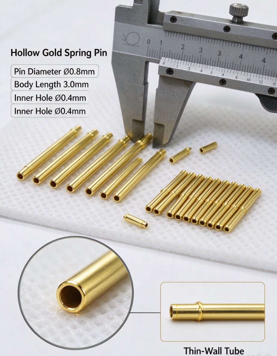
1. Prepare the Fixture Plate and Receptacles
Before any pin is inserted, the fixture plate must be machined and inspected. Push-in Spring Loaded Pogo Pins rely on an interference fit with the receptacle, so hole diameter and depth directly affect alignment and contact stability.
| Step | Action | Recommended Specification |
|---|---|---|
| 1 | Drill or machine receptacle holes | Diameter tolerance within ±0.02 mm of receptacle OD |
| 2 | Verify hole depth | Receptacle body fully seated, 0.2–0.5 mm below plate surface |
| 3 | Clean holes | Remove burrs, chips, and machining oil |
| 4 | Press in receptacles | Use an arbor press with a flat punch, perpendicular insertion |
| 5 | Inspect seating | No tilt, no protrusion above the plate surface |
Qiyiguo recommends matching each Push-in Spring Loaded Pogo Pin to its specified receptacle rather than forcing a pin into an undersized hole, which can deform the barrel and reduce spring travel.
2. Insert the Pogo Pins
-
Align the Push-in Spring Loaded Pogo Pin vertically with the receptacle bore.
-
Press the pin in with a controlled press or dedicated insertion tool; never strike it with a hammer.
-
Confirm the pin sits at the correct height relative to the fixture datum.
-
Check that the plunger moves freely through its full stroke after insertion.
3. Set Spring Travel and Pre-Load
Proper pre-load ensures stable contact resistance. As a practical starting point, set working travel at roughly two-thirds of the maximum stroke.
| Parameter | Typical Guideline |
|---|---|
| Working travel | 60–70% of maximum stroke |
| Spring force at working travel | Matched to pad size and board rigidity |
| Plunger alignment | Within 0.05 mm of pad center |
| Contact resistance target | Stable and repeatable across cycles |
4. Verify Electrical and Mechanical Performance
After assembly, run a continuity check on every Push-in Spring Loaded Pogo Pin, measure contact resistance, and perform a short cycle test. Qiyiguo supplies pins with documented spring force and plating data, which simplifies incoming inspection and fixture validation.
Frequently Asked Questions
Q: Can Push-in Spring Loaded Pogo Pins be replaced without disassembling the fixture?
A: Yes. Because Push-in Spring Loaded Pogo Pins are held by a press-fit receptacle rather than solder, a worn pin can be extracted with a dedicated removal tool and replaced from the front of the fixture, keeping downtime short.
Q: What hole tolerance is required for a Push-in Spring Loaded Pogo Pin?
A: The receptacle hole should be machined within about ±0.02 mm of the receptacle outer diameter, with a clean bore and sufficient depth for full seating; tighter control prevents tilt and preserves spring travel.
Q: How many cycles can Push-in Spring Loaded Pogo Pins withstand in a PCB test fixture?
A: Cycle life depends on stroke, spring force, plating, and current load, but Qiyiguo Push-in Spring Loaded Pogo Pins with hard gold plating typically deliver tens of thousands to over one hundred thousand reliable cycles when operated within rated travel.
Contact Us
For receptacle-matched Push-in Spring Loaded Pogo Pins, custom spring force, and fixture-ready specifications, contact Qiyiguo today and share your pad pitch, travel, and current requirements for a tailored recommendation.
