

How Does a Steering Hydraulic Cylinder Amplify Driver Input?
2026-10-08
A driver applies a force of 20 to 50 newtons to the steering wheel. That force is transmitted through the steering column to the steering gear, and then to the Steering Hydraulic Cylinder. The cylinder then generates a force of 5,000 to 20,000 newtons to turn the wheels. The amplification factor is 100 to 400 times. This is not magic. It is the result of hydraulic pressure acting on a larger area. But the amplification is not constant. It changes with engine speed, steering angle, and vehicle speed. This guide explains how the amplification works and how it is controlled to provide good steering feel.
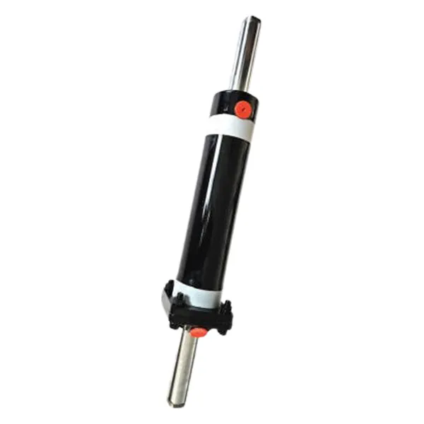
1. What Is the Force Path From Driver Input to Hydraulic Amplification?
The driver's input begins at the steering wheel. The torque applied to the steering wheel is transmitted through the steering column to the steering gear. The steering gear can be a recirculating ball type or a rack and pinion type. In both cases, the driver's input moves a control valve. The control valve directs hydraulic fluid from the pump to the Steering Hydraulic Cylinder. The cylinder then applies force to the steering linkage, which turns the wheels. The key is that the driver's input does not directly turn the wheels. It controls the valve, and the valve controls the cylinder. The cylinder does the work. The table below shows the force at each stage for a typical passenger car.
| Stage | Typical force or torque | Notes |
| Driver input at steering wheel | 30 N (tangential force) | Equivalent to 5 Nm torque on a 350 mm wheel |
| Steering column torque | 5 Nm | After mechanical advantage of the wheel |
| Steering gear input torque | 5 Nm | Directly coupled to the column |
| Hydraulic pressure | 80 bar | Generated by the pump; controlled by the valve |
| Steering Hydraulic Cylinder force | 10,000 N | Pressure times piston area |
| Force at tire contact patch | 8,500 N | After linkage ratio and friction losses |
In our factory, we test the force amplification of Steering Hydraulic Cylinder units on a test rig that measures input torque and output force. The amplification factor is calculated as the output force divided by the input force at the steering wheel. For a typical passenger car cylinder with a 40 mm bore and 80 bar pressure, the output force is 10,000 N. The input force at the wheel is 30 N, so the amplification factor is 333. This is the fundamental reason why hydraulic steering reduces driver effort.
2. How Does the Control Valve Modulate the Amplification?
The amplification is not always at its maximum. The control valve modulates the flow and pressure to the Steering Hydraulic Cylinder based on the driver's input and the vehicle speed. When the driver turns the wheel slowly, the valve opens a small amount, and the pressure in the cylinder is low. The amplification is low, which provides good feedback to the driver. When the driver turns the wheel quickly, the valve opens more, and the pressure increases. The amplification is higher, which reduces the effort required. The table below shows the relationship between valve opening and amplification.
| Valve opening | Hydraulic pressure | Cylinder force | Amplification factor |
| 10% | 20 bar | 2,500 N | 83 |
| 30% | 40 bar | 5,000 N | 167 |
| 50% | 60 bar | 7,500 N | 250 |
| 70% | 80 bar | 10,000 N | 333 |
| 100% | 100 bar | 12,500 N | 417 |
The control valve also includes a torsion bar that connects the steering wheel to the valve spool. The torsion bar twists as the driver applies torque. The amount of twist determines the valve opening. A stiffer torsion bar requires more driver effort to achieve the same valve opening, which increases steering feel. A softer torsion bar requires less effort but provides less feedback. In our factory, we manufacture Steering Hydraulic Cylinder units with different torsion bar stiffness to match the vehicle's steering feel requirements. Raydafon Technology Group Co.,Limited provides torsion bar specifications and recommended valve opening curves for different vehicle types.
3. How Does Vehicle Speed Affect the Amplification?
At low speeds, the driver needs high amplification to turn the wheels with minimal effort. At high speeds, the driver needs lower amplification to avoid oversteering. The steering system achieves this through a speed-sensitive valve or an electronic control unit. The speed-sensitive valve reduces the hydraulic pressure at high speeds, which reduces the amplification. The table below shows the amplification at different vehicle speeds for a typical passenger car.
| Vehicle speed | Hydraulic pressure | Cylinder force | Amplification factor | Driver effort at wheel |
| 0 – 10 km/h (parking) | 90 bar | 11,300 N | 377 | 15 N |
| 30 km/h (city) | 70 bar | 8,800 N | 293 | 22 N |
| 60 km/h (suburban) | 50 bar | 6,300 N | 210 | 30 N |
| 100 km/h (highway) | 30 bar | 3,800 N | 127 | 45 N |
| 140 km/h (high speed) | 20 bar | 2,500 N | 83 | 60 N |
At parking speed, the amplification is high, and the driver effort is low. At highway speed, the amplification is lower, and the driver effort is higher. This provides a stable steering feel at high speed and easy maneuverability at low speed. In our factory, we test Steering Hydraulic Cylinder units with electronic pressure control valves that adjust the pressure based on vehicle speed. Raydafon Technology Group Co.,Limited supplies these valves with our cylinders for applications that require speed-sensitive steering.
4. What Are the Design Parameters That Determine the Amplification?
The amplification factor is determined by three design parameters: the piston area of the Steering Hydraulic Cylinder, the maximum pressure of the pump, and the mechanical advantage of the steering linkage. The piston area is determined by the bore diameter. A larger bore produces more force for the same pressure. The maximum pressure is determined by the pump and the relief valve. A higher pressure produces more force for the same piston area. The mechanical advantage is determined by the geometry of the steering arms and the linkage. A higher mechanical advantage produces more force at the tire contact patch for the same cylinder force. The table below shows the effect of these parameters on the amplification factor.
| Design parameter | Typical range | Effect on amplification | Trade-off |
| Cylinder bore diameter | 30 – 60 mm | Proportional to area | Larger bore increases weight and fluid volume |
| Maximum pump pressure | 80 – 150 bar | Proportional to pressure | Higher pressure increases component stress |
| Steering linkage ratio | 1:1 to 1:3 | Proportional to ratio | Higher ratio reduces road feel |
| Torsion bar stiffness | 1.5 – 3.5 Nm/degree | Inversely proportional to driver effort | Softer bar reduces feedback |
Design tip: When specifying a Steering Hydraulic Cylinder for a new vehicle, start with the required tire force. Calculate the required cylinder force by dividing the tire force by the linkage ratio. Then calculate the required piston area by dividing the cylinder force by the working pressure. Finally, select the bore diameter that provides the required area. Our factory can provide a sizing calculation for your specific application.
Frequently Asked Questions About Steering Hydraulic Cylinder Amplification
Summary for Steering System Engineers
The Steering Hydraulic Cylinder amplifies driver input by converting hydraulic pressure into force. The amplification factor is determined by the piston area, the hydraulic pressure, and the linkage ratio. The control valve modulates the pressure based on driver input and vehicle speed to provide good steering feel. The torsion bar stiffness determines the driver effort required to open the valve. By understanding these relationships, engineers can design a steering system that provides low effort at parking speed and stable feel at highway speed. Raydafon Technology Group Co.,Limited has been manufacturing Steering Hydraulic Cylinder units for over 20 years and provides full engineering support for steering system design.
Raydafon Technology Group Co.,Limited manufactures Steering Hydraulic Cylinder units with a range of bore diameters, torsion bar stiffnesses, and valve configurations. We provide force calculations and steering feel recommendations for our customers.
