

How Does Box-type Transformer Substation Survive 20kA Short-Circuit Events?
2026-09-24
A 20kA short circuit is not a gradual event. It is a violent, millisecond-scale release of energy that imposes extreme mechanical and thermal stress on every component in the fault path. In a Box-type Transformer Substation, the fault current flows from the transformer secondary winding through the busbars, the circuit breakers, and the cables. Each component must withstand the electromagnetic forces that try to bend the busbars, the thermal energy that tries to melt the conductors, and the dynamic shock that tries to loosen the connections. The substation survives because the components are designed with specific withstand ratings, and because the protection system clears the fault before the energy exceeds those ratings. This guide explains the physics of short-circuit withstand and the design features that make it possible.
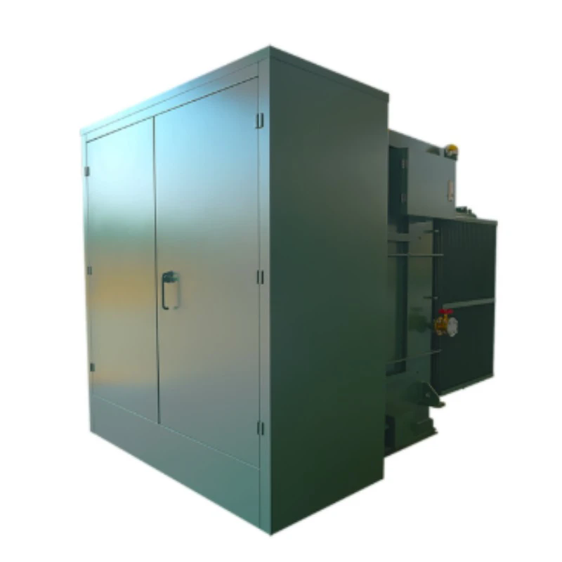
1. What Happens During the First 100 Milliseconds of a 20kA Short Circuit?
The short circuit begins when the insulation between two phases or between a phase and ground breaks down. The fault current rises from zero to its peak value in less than 10 milliseconds. The peak value is determined by the system impedance and the point on the voltage wave where the fault occurs. For a 20kA symmetrical fault current, the peak asymmetrical current can reach 40kA or more. This peak current produces an electromagnetic force between the conductors that is proportional to the square of the current. The force is enormous: for two parallel busbars carrying 40kA peak, the force per meter can exceed 5,000 N. This force tries to push the busbars apart or pull them together, depending on the current direction. The busbar supports and the enclosure must be designed to resist this force. The table below shows the peak force and the thermal energy for different fault current levels.
| Fault current (kA symmetrical) | Peak asymmetrical current (kA) | Peak electromagnetic force (N per meter) | Thermal energy (I²t) for 100 ms (kA²s) |
| 10 | 20 | 1,250 | 10 |
| 16 | 32 | 3,200 | 25.6 |
| 20 | 40 | 5,000 | 40 |
| 25 | 50 | 7,800 | 62.5 |
| 31.5 | 63 | 12,400 | 99.2 |
In our factory, we test the busbar supports and the enclosure of every Box-type Transformer Substation with a short-circuit withstand test. The test is performed according to IEC 62271-200. The substation must withstand the peak current and the thermal energy without permanent deformation or dielectric failure.
2. How Do Busbars and Supports Resist the Electromagnetic Forces?
The busbars in a Box-type Transformer Substation are the primary current-carrying conductors. They must resist both the electromagnetic forces and the thermal energy of the short circuit. The electromagnetic force is resisted by the busbar supports, which are spaced at intervals along the busbar length. The supports are made from high-strength insulating material, such as epoxy resin or fiberglass-reinforced polyester. The spacing between supports is determined by the peak force and the allowable deflection of the busbar. For a 20kA fault, the maximum support spacing for a copper busbar is typically 300 to 400 mm. The table below shows the relationship between fault current, busbar size, and support spacing.
| Fault current (kA) | Busbar size (mm x mm) | Maximum support spacing (mm) | Busbar material |
| 10 | 40 x 5 | 600 | Copper |
| 16 | 50 x 5 | 500 | Copper |
| 20 | 60 x 5 | 400 | Copper |
| 25 | 80 x 5 | 350 | Copper |
| 31.5 | 100 x 10 | 300 | Copper |
The thermal energy is resisted by the cross-sectional area of the busbar. The temperature rise during the short circuit must not exceed the allowable limit for the busbar material. For copper, the maximum allowable temperature is 250°C for a duration of 1 second. The busbar must be sized so that the I²t energy does not cause the temperature to exceed this limit. In our factory, we calculate the temperature rise for each busbar configuration and verify it with a type test.
3. How Does the Protection System Clear the Fault Before Damage Occurs?
The protection system is the second line of defense. Even the most robust busbar cannot withstand a short circuit indefinitely. The protection system must detect the fault and trip the circuit breaker within the withstand time of the equipment. For a Box-type Transformer Substation, the protection system typically includes overcurrent relays, earth fault relays, and a transformer differential relay. The overcurrent relay detects the fault current and sends a trip signal to the circuit breaker. The circuit breaker opens the circuit and interrupts the fault current. The total clearing time is the sum of the relay detection time and the circuit breaker opening time. For a modern vacuum circuit breaker, the opening time is 20 to 40 milliseconds. The relay detection time is 10 to 20 milliseconds. The total clearing time is 30 to 60 milliseconds. This is within the withstand time of the busbars and the transformer. The table below shows the coordination between the protection settings and the equipment withstand ratings.
| Equipment | Withstand time (ms) | Protection setting | Coordination margin |
| Transformer winding | 2,000 (thermal) | Differential relay: 20 ms | 1,980 ms |
| Busbar (20kA) | 1,000 (thermal) | Overcurrent relay: 15 ms | 985 ms |
| Circuit breaker | 40 (opening) | Trip signal: 10 ms | 30 ms |
| Current transformer | 500 (thermal) | Ratio: 400/5 | N/A |
In our factory, we test the protection coordination of every Box-type Transformer Substation with a secondary injection test. The test verifies that the relays operate within the specified time and that the circuit breaker opens within its rated time. We also provide a coordination study for each project to ensure that the protection settings are correct for the available fault current.
4. What Design Features Improve Short-Circuit Survival in a Box-type Transformer Substation?
There are four design features that improve short-circuit survival. The first is a rigid enclosure. The enclosure must resist the internal pressure that is generated by the arc if the fault is not cleared quickly. The enclosure is made from 2 to 3 mm thick steel and is tested for internal arc withstand according to IEC 62271-200. The second is arc-resistant construction. The substation can be designed with arc-resistant features, such as pressure relief flaps, that direct the hot gases away from the operator. The third is a robust busbar support system. The supports must be spaced closely enough to prevent busbar deflection. The fourth is a fast-acting protection system. The faster the fault is cleared, the less energy the equipment must withstand. In our factory, we offer all of these design features as options. We also provide a short-circuit withstand calculation for each project.
Frequently Asked Questions About Box-type Transformer Substation Short-Circuit Survival
Summary for Substation Engineers
A Box-type Transformer Substation survives a 20kA short circuit through a combination of robust design and fast protection. The busbars and supports resist the electromagnetic forces. The cross-sectional area of the conductors limits the temperature rise. The protection system clears the fault before the thermal energy exceeds the withstand rating. The enclosure resists the internal pressure. By understanding these factors and verifying the ratings, engineers can ensure that the substation will survive a short-circuit event without catastrophic failure. Lugao Power Co.,Ltd. has been manufacturing Box-type Transformer Substation units for over 18 years and provides full short-circuit withstand testing and coordination studies.
Lugao Power Co.,Ltd. manufactures Box-type Transformer Substation units with short-circuit withstand ratings up to 31.5kA. We provide type test reports, coordination studies, and arc-resistant options for critical applications.
