

How Does Hydraulic Control Response Affect Lifting Smoothness?
2026-09-22
Ask any operator of a scissor lift, a dump truck, or a hydraulic press what bothers them most, and the answer is rarely about capacity or speed. It is about smoothness. A hydraulic lift cylinder that jerks at the start, drops with a thud at the end, or creeps slowly when it should hold still is not just uncomfortable. It is a sign that the hydraulic control response is mismatched to the load and the circuit. The smoothness of a lift is determined by how quickly and accurately the control valve responds to a command, how the cylinder cushions the end of stroke, and how the oil and structure interact. This guide is written for field engineers and maintenance technicians who need to diagnose and correct smoothness problems in real equipment.
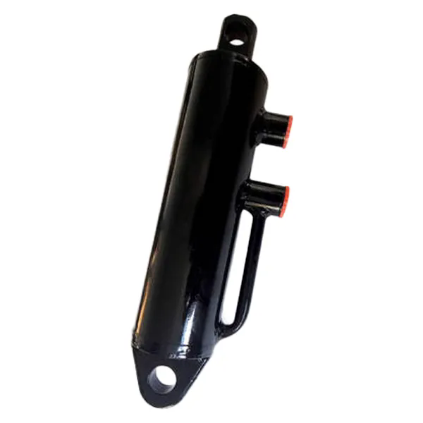
1. What Causes Jerking at the Start of a Lift Stroke?
Jerking at the start of a stroke is the most common complaint. It occurs when the hydraulic lift cylinder receives a pressure signal that rises faster than the load can be accelerated smoothly. There are three primary causes. The first is a valve with a step response that is too fast. A solenoid valve that opens in 20 milliseconds sends a sudden surge of oil to the cylinder, which produces a sharp acceleration. The second is air in the system. Trapped air compresses and expands, causing the cylinder to move in fits and starts. The third is insufficient back pressure on the return side. When the load is lowered, the cylinder can run ahead of the oil supply, creating a vacuum that collapses and causes a jerk. The table below shows the relationship between valve response time and perceived jerk.
| Valve response time | Perceived jerk level | Typical application | Recommended adjustment |
| < 20 ms | Severe | High-speed pressing | Add ramp control or use proportional valve |
| 20 – 50 ms | Moderate | General lifting | Add accumulator or adjust ramp |
| 50 – 100 ms | Slight | Precision positioning | Acceptable for most applications |
| > 100 ms | None | Heavy load lifting | No adjustment needed |
In our factory, we test the response time of every hydraulic lift cylinder with a servo valve and a pressure transducer. The test records the pressure rise from 10 percent to 90 percent of the command signal. We use this data to recommend the correct valve and ramp settings for each application.
2. Why Does the Load Drop Suddenly at the End of the Stroke?
A sudden drop at the end of a stroke is caused by the loss of cushioning. Most hydraulic lift cylinder units have a cushion at the end of the stroke that traps oil in a small chamber and forces it through a narrow orifice. This slows the cylinder as it approaches the end of travel. If the cushion is worn, misadjusted, or missing, the cylinder will hit the end stop at full speed, producing a shock that can damage the structure and the seals. The table below shows the effect of cushion condition on end-of-stroke shock.
| Cushion condition | Deceleration distance | Peak shock pressure | Perceived smoothness |
| New and properly adjusted | 25 – 40 mm | 1.2x working pressure | Smooth |
| Worn cushion seal | 10 – 15 mm | 2.5x working pressure | Moderate thud |
| Missing cushion | 0 mm | 5x working pressure | Severe shock |
| Cushion screw too open | 5 – 10 mm | 3x working pressure | Hard stop |
Raydafon manufactures hydraulic lift cylinder units with adjustable cushioning at both ends of the stroke. Our factory sets the cushion screw to the recommended position before shipment and provides a field adjustment guide. The cushion can be adjusted by turning the screw clockwise to increase the deceleration or counterclockwise to decrease it.
3. What Causes Creeping When the Cylinder Should Hold Still?
Creeping is the slow movement of the cylinder when the control valve is in the neutral position. It is caused by internal leakage in the valve or the cylinder. In a hydraulic lift cylinder, the piston seal separates the extend and retract chambers. If the seal is worn or damaged, oil can leak from one chamber to the other, causing the cylinder to drift. In the valve, the spool clearance may be too large, allowing oil to bypass the land. Creeping is not just a nuisance. It can be a safety hazard if the cylinder is holding a load. The table below shows the acceptable leakage rates for different applications.
| Application | Maximum allowable creep rate | Typical cause | Corrective action |
| Holding a suspended load | 0 mm/hour | Piston seal leak | Replace piston seal |
| Positioning a work platform | < 1 mm/hour | Valve spool leak | Replace valve or adjust clearance |
| General lifting | < 5 mm/hour | Normal wear | Monitor; replace if exceeds limit |
| Non-critical application | < 20 mm/hour | Minor seal wear | Schedule maintenance |
In our factory, we test every hydraulic lift cylinder for internal leakage at 1.5 times the rated pressure. The maximum allowable leakage is 0.1 liters per minute for a standard cylinder. If the leakage exceeds this value, the cylinder is rejected and the seals are replaced.
4. How Do Oil Viscosity and Temperature Affect Lifting Smoothness?
The viscosity of the hydraulic oil affects the response of the entire system. If the oil is too thick, the pressure drop through the lines and valves increases, which slows the response and can cause jerking. If the oil is too thin, the internal leakage increases, which causes creeping and loss of cushioning. The viscosity is determined by the oil grade and the operating temperature. A system that is smooth at 40°C may become jerky at 10°C because the oil viscosity doubles. The table below shows the effect of temperature on viscosity and smoothness.
| Oil temperature | Viscosity (ISO VG 46) | Effect on smoothness | Recommended action |
| 10°C | 180 cSt | Jerky, slow response | Warm up or use lower viscosity oil |
| 25°C | 80 cSt | Good | None |
| 40°C | 46 cSt | Excellent | Normal operating range |
| 60°C | 22 cSt | Creeping, reduced cushioning | Cool the oil or use higher viscosity oil |
Raydafon Technology Group Co.,Limited recommends ISO VG 46 oil for most hydraulic lift cylinder applications. For cold climates, we recommend ISO VG 32. For high-temperature applications, we recommend ISO VG 68. Our factory provides a viscosity-temperature chart with every cylinder so that customers can verify the oil selection for their operating conditions.
Frequently Asked Questions About Hydraulic Lifting Smoothness
Summary for Field Engineers and Maintenance Technicians
Lifting smoothness in a hydraulic system is determined by the control response of the valve, the condition of the cylinder cushioning, the internal leakage of the cylinder and valve, and the viscosity of the oil. Jerking at the start is usually caused by a valve that is too fast or air in the system. A sudden drop at the end is caused by worn or misadjusted cushioning. Creeping is caused by internal leakage. Temperature affects all of these factors by changing the oil viscosity. By diagnosing the specific symptom and adjusting the relevant parameter, most smoothness problems can be corrected without replacing the cylinder. Raydafon Technology Group Co.,Limited has been manufacturing hydraulic lift cylinder units for over 20 years and provides full technical support for smoothness optimization.
Raydafon Technology Group Co.,Limited manufactures hydraulic lift cylinder units with adjustable cushioning, low-friction seals, and precision honed bores. We provide response time data and viscosity charts for all of our products.
