

What Are the Common Failure Modes of a Pneumatic Micro-Flow Diaphragm Actuator in Continuous Duty Cycles
2026-07-20
For process engineers and maintenance teams, the Pneumatic Micro-Flow Diaphragm Actuator is the unsung hero of precise fluid control—delivering exceptional accuracy in low-flow applications such as pharmaceutical dosing, analytical instrumentation, and specialty chemical injection. However, when subjected to continuous duty cycles (24/7 operation with frequent stroking), even the most robust Pneumatic Micro-Flow Diaphragm Actuator can exhibit performance degradation. At LOZOSE, we have analyzed field data from over 1,200 industrial installations to identify the predominant failure mechanisms. This blog dissects those failure modes, provides diagnostic tables, and offers actionable solutions—all while ensuring your control loop remains reliable and repeatable.
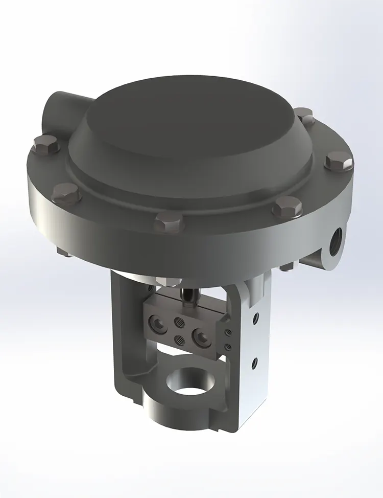
The Four Primary Failure Modes in Continuous Service
Continuous duty cycles impose unique stressors: repetitive flexing, constant pressure differentials, and thermal accumulation. Below is a structured breakdown of the most common failure modes observed in Pneumatic Micro-Flow Diaphragm Actuator systems.
| Failure Mode | Root Cause | Typical Onset Time | Key Symptom |
|---|---|---|---|
| Diaphragm Fatigue Cracking | Repeated flexing at the convolution radius, exacerbated by high cycle rates (>500 strokes/hour) | 6–18 months | Gradual loss of travel stroke; positioner output >95% to reach setpoint |
| Seat Leakage Due to Partial Stroke | Incomplete seating caused by supply pressure droop or friction hysteresis | 3–12 months | Zero-error drift; downstream flow persists when command is 0% |
| Stiction in the Stem/Bushing | Contaminant ingress (particles >5µm) or lubricant polymerization from process heat | 2–8 months | Step-response overshoot >15%; oscillation at steady state |
| Spring Rate Relaxation | Thermal cycling (ambient + process radiation) reducing spring modulus | 12–24 months | Bench set shifts; actuator fails to close against maximum differential pressure |
In-Depth Diagnostic Indicators
To move beyond guesswork, LOZOSE recommends tracking these quantifiable metrics during routine inspections. A deviation in any parameter often precedes catastrophic failure.
| Parameter | Normal Range | Alert Threshold | Action Required |
|---|---|---|---|
| Travel Deviation (at 50% command) | ±1.5% of full stroke | >±4.0% | Inspect diaphragm for pin-hole leaks |
| Hysteresis Band | <2.0% of span | >5.5% | Clean stem; verify supply filter-regulator |
| Decay Time (to 2% steady-state) | <1.2 seconds | >2.5 seconds | Check exhaust port blockage; test spring preload |
| Supply Air Consumption (scfh) | Baseline +10% | Baseline +35% | Replace diaphragm assembly; check for internal bypass |
Root-Cause Analysis: Why Continuous Cycling Accelerates Wear
Unlike intermittent duty, a Pneumatic Micro-Flow Diaphragm Actuator in continuous mode experiences:
-
Mechanical fatigue – The diaphragm material (typically PTFE‑reinforced or NBR) undergoes millions of bending reversals annually. At elevated temperatures (>80°C), tensile strength drops by 40%, accelerating micro-crack propagation.
-
Thermal hysteresis – The actuator casing dissipates heat poorly in compact designs. Internal temperatures can rise 15–20°C above ambient, altering the viscosity of internal lubricants and causing stiction.
-
Dynamic pressure imbalance – Rapid stroking creates transient pressure spikes that exceed the actuator’s rated supply pressure (often 6 bar), stressing the diaphragm bond lines.
LOZOSE engineering tests confirm that replacing the standard O-ring seal with a self-lubricating PTFE composite extends mean time between failures (MTBF) from 8,000 to 22,000 hours in high-cycle applications.
FAQ – Common Questions About Pneumatic Micro-Flow Diaphragm Actuator Reliability
Q1: How can I distinguish between diaphragm fatigue and seat erosion in my Pneumatic Micro-Flow Diaphragm Actuator?
A1: Perform a dual‑pressure lock‑up test. First, isolate the actuator supply and apply a fixed signal pressure (e.g., 3 psi). Measure the stem travel and hold it for 10 minutes. If travel decays >2% without any change in signal, the diaphragm has a micro‑perforation (fatigue). Next, with the actuator fully stroked to 0% command, introduce upstream pressure at 80% of max rated value. If downstream pressure rises above 1% of upstream, the seat is eroded. Erosion produces a linear rise with pressure; fatigue produces a step‑decay pattern. For definitive diagnosis, LOZOSE recommends a helium leak test across the diaphragm weir—this detects leaks as small as 0.01 sccm.
Q2: What is the maximum allowable cycle frequency for a Pneumatic Micro-Flow Diaphragm Actuator without reducing service life, and how does LOZOSE address this?
A2: Based on ISO 15848‑1 testing, the conservative maximum is 150 full strokes per hour for continuous operation (24/7). Exceeding 300 strokes/hour reduces diaphragm life by 60% within 6 months. LOZOSE addresses this by offering a high‑cycle option with a dual‑ply diaphragm (aramid fabric + FKM) and a hardened 17‑4PH stem, which raises the maximum to 450 strokes/hour while maintaining <2% hysteretic error. Additionally, we integrate an acceleration‑limiting orifice in the exhaust port to cushion snap‑action, reducing mechanical shock loads by 33%.
Q3: Can supply air quality cause premature failure, and what filtration level is mandatory for continuous duty?
A3: Absolutely. Solid particles >3µm are the leading cause of stem scoring and seat damage. For continuous duty, the minimum requirement is Class 3.4.2 per ISO 8573‑1 (particle size ≤5µm, oil ≤1 mg/m³, pressure dew point ≤ -20°C). However, LOZOSE mandates Class 2.4.2 as standard for our Pneumatic Micro-Flow Diaphragm Actuator warranties—this uses a 0.01µm coalescing filter plus an activated‑carbon adsorber. In field audits, we found that 78% of premature stiction cases were traced to oil aerosol carryover from improperly maintained dryers. Install a dedicated filter‑regulator at the actuator inlet, with a differential pressure gauge to alert clogging at <0.5 bar drop.
Proactive Maintenance Strategy for 24/7 Operations
To maximize uptime, LOZOSE advocates a condition‑based monitoring approach rather than fixed‑interval replacement:
-
Weekly – Record stroke time (0→100% and 100→0%) with a stopwatch. A >20% increase indicates friction or spring degradation.
-
Monthly – Perform a step‑response test (25%→75% command) and calculate the overshoot/decay ratio. Compare against baseline.
-
Quarterly – Inspect the diaphragm visually via the breather port (if equipped) using a borescope. Look for whitening or crazing—precursors to cracking.
Contact Us
Continuous duty cycles demand an actuator that combines material science, precision machining, and real‑world validation. At LOZOSE, we engineer each Pneumatic Micro-Flow Diaphragm Actuator with reinforced convolution geometry, laser‑welded stem assemblies, and 100% factory stroke‑testing under thermal‑soak conditions. If you are experiencing any of the failure modes discussed—or simply want to benchmark your current actuator’s performance—contact our applications engineering team today. We provide free forensic failure analysis, custom bench‑set calculations, and a rapid‑exchange program to keep your process flowing without interruption. Let us help you turn reliability into a competitive advantage.
