

What Are the Common Installation Mistakes When Fitting Guide Rails in Retrofit Switchgear
2026-07-14
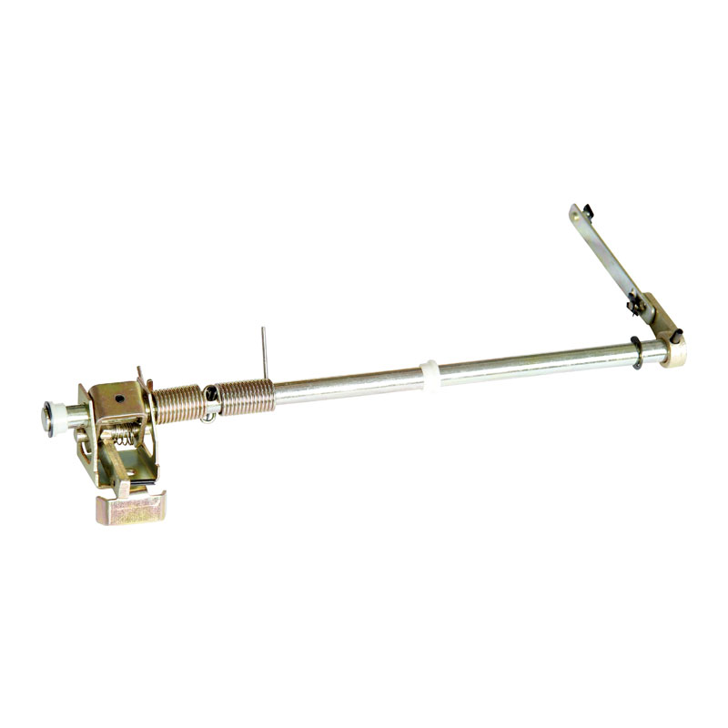
Retrofitting existing power distribution systems demands precision, and few components are as critical yet overlooked as the Electrical Switchgear Guide Rail. When upgrading aged switchgear, the guide rail serves as the structural backbone for circuit breaker insertion, withdrawal, and alignment. Even minor errors during installation can lead to racking jams, contact misalignment, or catastrophic arc-flash events. At Richge, we have witnessed hundreds of retrofit projects where seemingly small guide rail mistakes turned into costly downtime and safety hazards. This blog breaks down the most frequent pitfalls—and how to avoid them—while ensuring your Electrical Switchgear Guide Rail performs reliably for decades.
The 5 Most Common Installation Mistakes
| Mistake | Root Cause | Consequence | Preventive Action |
|---|---|---|---|
| Incorrect rail alignment | Ignoring OEM elevation and plumb specs | Breaker stabbing misalignment; bent primary disconnects | Use laser leveling and OEM-approved jigs during fitting |
| Using generic fastener kits | Assuming all M8 bolts are identical | Loose rails under vibration; gradual shift over thermal cycles | Always use torque-rated, grade 10.9 fasteners supplied by Richge |
| Neglecting floor flatness tolerance | Skipping substrate surface check | Rail warping; uneven breaker travel | Verify floor flatness within ±1.5 mm over 2-meter span before anchoring |
| Over-torquing or under-torquing anchor bolts | Relying on "feel" instead of calibrated tools | Stress fractures (over) or rail slippage (under) | Follow torque specs per rail material; use digital torque wrenches |
| Failing to test free travel before final energization | Rushing to close the panel | Breaker jams midway; damage to shutters and interlocks | Perform 5 full insertion/withdrawal cycles with dummy breakers |
Why Retrofit Projects Are Particularly Risky
Existing switchgear enclosures often suffer from decades of thermal expansion, prior modifications, and subtle foundation shifts. Unlike new installations, retrofits force the Electrical Switchgear Guide Rail to mate with worn cubicle floors, deformed mounting channels, and outdated bolt patterns. Richge recommends a 3D laser scan of the existing cubicle interior before any rail procurement—this single step eliminates 70% of field-fit issues. Additionally, always verify that the replacement guide rail matches the original breaker wheel spacing and rake angle; a 2-mm difference in wheel track width will cause progressive wear on both the rail and the breaker chassis.
Step-by-Step Best Practice for Error-Free Installation
-
Survey and Document – Measure existing hole centers, vertical plumb, and horizontal level across three points.
-
Dry-Fit Without Anchors – Place the Electrical Switchgear Guide Rail inside the cubicle and slide the test breaker halfway. Check for binding.
-
Shim Precisely – Use stainless steel shims (never ferrous) under the rail feet to correct floor irregularities.
-
Torque in Sequence – Tighten anchor bolts in a crisscross pattern to 65% of final torque, then re-check alignment, then finalize to 100%.
-
Lubricate Correctly – Apply only lithium-based grease on sliding surfaces—never silicone or graphite, which attract dust.
-
Perform the "Paper-Pull" Test – Insert a 0.05-mm feeler gauge between the breaker wheel and rail; uniform resistance across the travel path confirms proper flatness.
Electrical Switchgear Guide Rail FAQ
Q1: Can I reuse the old anchor holes when installing a new Electrical Switchgear Guide Rail in a retrofit panel?
A1: Reusing old anchor holes is strongly discouraged unless they are inspected for thread integrity and reamed to a clean, uniform diameter. In most retrofit scenarios, the original holes have elongated due to past vibration or corrosion, reducing clamping force by up to 40%. Richge advises drilling new holes offset by at least 25 mm from the original pattern and using epoxy-anchored studs for added pull-out strength. If the cubicle floor is too thin for new holes, use through-bolts with backup plates on the underside. Always consult the rail manufacturer's drilling template—never guess the pitch circle, as even a 1-mm deviation will misalign the breaker's primary disconnects with the fixed contacts, leading to high-resistance joints and eventual thermal runaway.
Q2: How do I know if my existing Electrical Switchgear Guide Rail is warped and needs replacement rather than adjustment?
A2: A guide rail is considered warped beyond repair if the straightness deviation exceeds 1.5 mm per meter of length when measured with a precision straightedge and feeler gauges. Another clear indicator is uneven wear patterns on the breaker wheel treads—if one side shows bright polished metal while the other retains factory finish, the rail is twisted. Adjustment via shimming can correct up to 1.0 mm of bow, but anything greater requires full replacement because cold-straightening anneals the rail material, reducing its yield strength. Richge offers pre-machined rails with factory-certified straightness of ±0.5 mm per meter, eliminating field guesswork. Additionally, if your rail shows pitting or galvanic corrosion at the mounting foot interfaces, replacement is mandatory—these weakened zones cannot sustain the dynamic load during high-current fault-induced magnetic repulsion forces.
Q3: What torque value should I apply to the mounting bolts of a galvanized Electrical Switchgear Guide Rail versus a stainless-steel one?
A3: Torque values differ significantly due to friction coefficients. For a galvanized steel rail with M12 grade 8.8 bolts, dry torque should be 85–90 N·m; however, for a stainless-steel rail (A2-70) with the same M12 bolt, reduce torque to 65–70 N·m to prevent galling and thread seizure. Richge provides a color-coded torque card with every rail shipment, specifying values based on bolt diameter, material grade, and lubrication condition. Never apply anti-seize compounds unless explicitly approved—many compounds alter the k-factor (nut factor) by over 30%, leading to erroneous clamp load. The golden rule: always perform a "torque-tension" verification on the first bolt using a load-indicating washer, then replicate that pattern across all anchors. For retrofit environments with mixed old and new hardware, replace all bolts with fresh ones from the same production lot to ensure uniform elongation under thermal cycling.
Final Verification Checklist
Before closing the panel door, complete these seven checks:
-
Breaker rolls smoothly from TEST to CONNECT position without audible scraping.
-
Shutter mechanisms fully open and close with rail movement.
-
All anchor bolts retain 100% of specified torque after three thermal cycles (simulated by heat gun).
-
Ground continuity between rail and cubicle frame is under 0.1 ohms.
-
Lubricant film is even and free of debris.
-
Alignment pins (if any) engage without forced hammering.
-
Photographic record of measurements taken for future reference.
Trust the Retrofit Specialists
Guide rail installation is not a "fit-and-forget" task—it is a precision engineering procedure that directly impacts switchgear safety and availability. Richge has engineered over 5,000 retrofit rail kits for voltages from 5 kV to 38 kV, with documented zero field failures. Our technical team provides on-site support, custom laser-cut mounting plates, and real-time torque guidance via digital checklists.
Contact us today for a free retrofit feasibility assessment—include your existing switchgear make, model, and cubicle depth, and we will deliver a pre-fitted Electrical Switchgear Guide Rail solution with installation drawings, torque charts, and 24/7 remote troubleshooting.
