

What Is the Role of Silicon Carbide Coating in Silicon Epitaxy Processes?
2026-11-09
A silicon epitaxy engineer reviews a particle map from a production run. The pattern shows a ring of defects near the edge of the wafer and a cluster near the center. The gas flows are within specification. The temperature profile has not changed. The engineer removes the susceptor and inspects the surface. The graphite beneath the Silicon Carbide Coating is exposed at a small area near the edge. The exposed graphite releases carbon particles during the high temperature step, and those particles land on the wafer. In our factory, we have seen this failure mode many times, and it is the reason the coating is treated as a functional barrier rather than a cosmetic finish. WuYi TianYao New Material Tech.Co.,Ltd. has been producing coated susceptors for over 10 years.
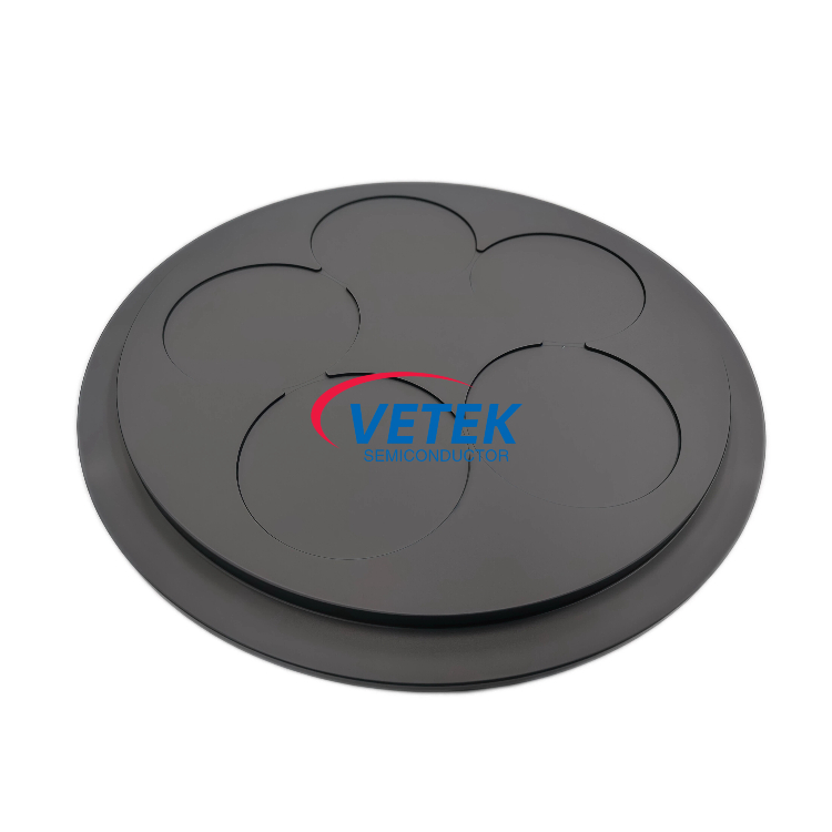
1. Why Does a Coating Matter More Than the Graphite Beneath It in Silicon Epitaxy?
The susceptor in a silicon epitaxy reactor is usually made from high purity graphite. Graphite has excellent thermal shock resistance and a low coefficient of thermal expansion, but it is porous. At the process temperature, which can exceed 1,100 degrees Celsius, the graphite can release carbon particles and trace metal impurities. Those particles and impurities can land on the wafer and create stacking faults, haze, or electrical defects. The Silicon Carbide Coating seals the graphite surface and provides a chemically inert barrier. The barrier prevents direct contact between the process gas and the graphite. It also provides a stable surface for wafer support and heat transfer. In our experience, the coating is the difference between a susceptor that lasts a few hundred runs and one that lasts several thousand runs.
2. How Do Coating Thickness and Surface Finish Change Epitaxial Layer Quality?
The thickness and the surface finish of the Silicon Carbide Coating directly influence the thermal contact and the particle performance. A coating that is too thin may contain pinholes. A pinhole allows the process gas to reach the graphite and creates a local contamination source. A coating that is too thick may develop residual stress and flake during thermal cycling. The surface finish controls the contact between the susceptor and the wafer. A rough surface creates local gaps that reduce heat transfer and cause temperature non uniformity. A smooth surface improves contact and reduces particle generation. In our factory, we specify a coating thickness of 80 to 150 microns and a surface roughness of Ra 0.2 to 0.5 micron. Our test data shows that this window provides a good balance of barrier integrity, thermal contact, and mechanical durability.
| Parameter | Typical value | Why it matters |
| Coating thickness | 80 to 150 microns | Thin layers risk pinholes; thick layers risk stress and flaking |
| Coating purity | 6N | Reduces metal contamination on the wafer |
| Density | 3.20 grams per cubic centimeter minimum | High density closes porosity and limits gas penetration |
| Surface roughness | Ra 0.2 to 0.5 micron | Improves thermal contact and reduces particle adhesion |
| Porosity | Below 0.5 percent | Prevents process gas from reaching the graphite |
| Thermal conductivity | 120 to 200 watts per meter kelvin | Supports uniform heat transfer to the wafer |
| Coefficient of thermal expansion | 4.0 to 4.5 ppm per degree Celsius | Reduces stress at the coating and graphite interface |
| Adhesion strength | Above 50 megapascals | Prevents flaking during thermal cycling |
3. What Failure Modes Point to the Coating Rather Than the Reactor?
Not every defect is caused by the coating. The engineer must distinguish between reactor issues and coating issues. A coating related failure usually appears as particles concentrated near the susceptor contact points, as haze on the wafer backside, or as a local temperature anomaly. A reactor issue usually appears as a uniform shift across the wafer or as a gas flow pattern that changes with the recipe. Our failure analysis process starts with a surface inspection of the susceptor, followed by a particle count on a test wafer, and then a cross section of the coating at the suspect area. At WuYi TianYao New Material Tech.Co.,Ltd., we keep field returns and compare the coating condition with the process history. This comparison often shows whether the coating was damaged by handling, by thermal cycling, or by a cleaning step that was too aggressive.
| Observed symptom | Likely coating cause | Verification method |
| Particles on wafer | Pinholes or local flaking | Surface particle count and scanning electron microscopy |
| Haze or roughness | Coating surface too rough | Atomic force microscopy or stylus profiler |
| Thickness drift across wafer | Non uniform coating or poor thermal contact | Cross section and thermal mapping |
| Metal contamination | Insufficient purity or substrate outgassing | Glow discharge mass spectrometry and secondary ion mass spectrometry |
| Cracking after cycling | Expansion mismatch or residual stress | Thermal cycling test and dye penetrant inspection |
4. How Should Engineers Qualify a Coating Before It Enters Production?
The qualification should start with the process window, not with the coating catalog. The engineer should define the maximum temperature, the number of thermal cycles, the cleaning chemistry, and the particle specification. The coating supplier should then provide the thickness, purity, density, roughness, and adhesion data for the proposed coating. The next step is a small batch trial. The trial should include at least three susceptors and at least 50 epitaxial runs. The wafers from each run should be measured for thickness uniformity, particle count, and haze. Our qualification protocol includes a cross section of the coating after the trial to verify that the interface has not degraded. We also recommend a thermal cycling test from room temperature to the process temperature for 100 cycles before the production release. VETEK supports this qualification with sample coatings and test reports.
5. Why Does Coating Quality Drift After Cleaning and Thermal Cycling?
The coating is stable, but it is not indestructible. The quality can drift after repeated cleaning and thermal cycling. A cleaning step that uses an aggressive acid or an abrasive brush can remove a thin layer of the coating and change the surface roughness. Thermal cycling can open microcracks at the interface if the coating has residual stress. Those microcracks become paths for the process gas and for metal impurities. The drift is usually slow, and it is not visible to the naked eye. Our records show that a coating can remain within specification for several thousand runs if the cleaning is controlled and the thermal profile is stable. WuYi TianYao New Material Tech.Co.,Ltd. recommends a periodic coating inspection every 500 runs, including a surface roughness measurement and a particle count on a test wafer. When the roughness exceeds the upper limit or the particle count rises, the susceptor should be recoated or replaced.
The role of the Silicon Carbide Coating in silicon epitaxy is to separate the process environment from the graphite substrate, to control particles and metal contamination, and to provide a stable thermal contact surface. The coating quality is defined by thickness, purity, density, roughness, and adhesion, and it must be qualified against the actual process window. The coating can drift after cleaning and thermal cycling, so periodic inspection is required. A well specified coating is not a consumable detail. It is a process control element that determines wafer yield and susceptor life.
