

What Machining Processes Help Improve Moldbase and Standard Part Dimensional Accuracy?
2026-11-18
Why Does Dimensional Accuracy Begin with the Machining Plan?
Dimensional accuracy in Moldbase and Standard Part manufacturing is not created by a single finishing operation. It is the result of a controlled process chain that links material condition, datum selection, rough machining, stress relief, finish machining and final inspection. A mold base may have the correct overall length and width yet still cause assembly problems if its plates are not flat, parallel or square. Likewise, guide pillars, guide bushes and ejector pins can meet their nominal diameters but fail to run smoothly when roundness, straightness or surface finish is inconsistent.
For mould makers and tooling engineers, the practical objective is repeatable fit across the complete assembly. Plate thickness, pocket depth, hole position, dowel locations and guide-component alignment all influence parting-line contact, cavity registration and ejection movement. The company supports mold manufacturing with mold bases, standard components and related precision machining services. Its published production information lists CNC machining, EDM, slow-wire cutting, grinding and coordinate measurement equipment. The correct process selection depends on the drawing, material, heat-treatment condition, required fit and inspection plan rather than on machine capability alone.
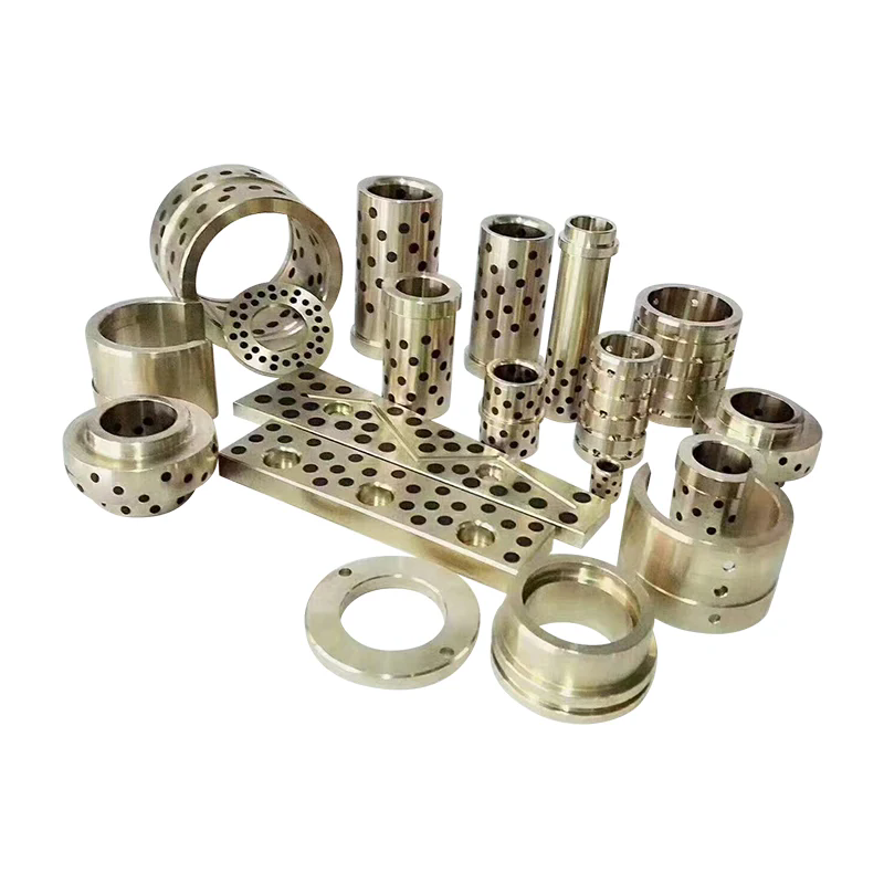
How Does CNC Milling Establish Accurate Plate Geometry?
CNC milling is usually the primary operation for producing the functional geometry of mold-base plates in a Moldbase and Standard Part order. It creates reference faces, outer profiles, pockets, counterbores, steps and mounting features. The most important decision is not simply which cutter to use; it is how the workpiece is located and how the machining sequence controls distortion. Our stable datum scheme allows the operator to machine related features from consistent references instead of repeatedly picking up uncertain edges.
For A plates, B plates, support plates and clamping plates, the sequence commonly starts with stock preparation and face milling. The first machined face becomes a reference for subsequent operations. The workpiece is then turned or repositioned using that reference to establish the opposite face and the required thickness. Where several plates must align as a stack, our machining plan should control the relationship between the plate faces, guide holes, bolt patterns and locating features. In our assembly reviews, a small positional error in one plate can accumulate when the complete mold is assembled.
In our process planning, the most important decision is not simply which cutter to use; excessive cutting force can deflect a thin plate or generate heat that changes its dimensions during the operation. Roughing and finishing passes should therefore be separated where the geometry or material condition makes this necessary. A consistent finishing allowance helps avoid uneven stock removal, while suitable clamping prevents the plate from being pulled out of shape. On large plates, machining strategy should also consider support points and the possibility of residual stress being released as material is removed.
Our production planning should treat critical features as a connected geometric system. For example, the guide pillar and guide bush locations need to relate correctly to the plate edges and cavity centreline; ejector-plate openings must align with the ejector system; and mounting holes must match the intended machine or tooling interface. CNC milling is effective for these features, but accuracy depends on workholding, datum transfer, tool condition, machine calibration and in-process checks. Moldburger Mold Industry Co., Ltd. identifies CNC equipment from Makino, Dawei and FANUC in its published production information, providing a machining base for complex plate and component work.
When Is Precision Grinding Necessary for Flatness and Fit?
For Moldbase and Standard Part production, precision grinding is used when a machined surface needs tighter control of flatness, parallelism, thickness or surface finish than milling alone is intended to provide. On mold-base plates, grinding the mating faces helps create a more reliable stack. If the A and B plates are not sufficiently flat and parallel, clamping load may not be distributed evenly. That can contribute to local gaps, uneven wear or inconsistent contact around the parting line. Grinding is also important for guide pillars, guide bushes and ejector pins, where dimensional consistency and surface condition affect sliding behaviour.
Surface grinding removes a small, controlled amount of material using an abrasive wheel. Our grinding route must account for wheel condition, dressing, feed rate, coolant delivery, workholding and the thermal behaviour of the workpiece. Too much heat can cause grinding burn or local distortion; poor wheel dressing can leave an uneven finish; and inadequate support can allow a slender component to deflect. For long guide components, cylindrical grinding is typically selected to control outside diameter, roundness and straightness. For flat plates, surface grinding is used to refine reference faces and establish a consistent thickness.
The target should be defined by function rather than by pursuing the smallest possible number on every dimension. A guide pillar needs a controlled running fit with its matching bush, while a wear plate may need a flat contact surface and suitable clearance for movement. An ejector pin requires a diameter and finish that allow reliable reciprocation without excessive looseness. A plate that is ground accurately but assembled against an incorrectly machined mating feature will not deliver a precise mold. Our inspection plan should therefore measure paired and related features, not just isolated dimensions.
Our factory lists Okamoto grinding machines and two Hexagon coordinate measuring machines in its production-equipment information. Grinding can establish the required surface geometry, while coordinate measurement can verify selected dimensions and geometric relationships against the engineering drawing. For a buyer, useful questions include whether the critical faces are ground after rough machining, how parallelism is checked, whether guide components are measured as matched features, and how inspection results are recorded for repeat orders. These process details are more meaningful than a general claim of high precision.
How Do Drilling, Boring and Wire EDM Control Hole Accuracy?
In Moldbase and Standard Part production, hole-making operations have a direct effect on mold assembly. Guide-pin holes, guide-bush seats, return-pin holes, ejector-pin bores, cooling channels and threaded mounting holes each have different functional requirements. Drilling is efficient for creating a hole, but it does not automatically guarantee accurate position, diameter or straightness. Where a hole needs a controlled size or a better surface, boring, reaming or a dedicated finishing operation may be required. The correct choice depends on the hole diameter, depth, material, tolerance and relationship to other features.
Accurate hole positioning begins with a reliable datum and a stable setup. If a plate is re-clamped between operations, the reference must be transferred carefully or the critical holes should be completed in a setup that preserves their relationship. Tool runout, drill-point geometry, chip evacuation and cutting-fluid delivery can all influence hole quality. Deep holes require particular attention because tool deflection and chip packing can cause the hole to wander or become tapered. For guide systems, the position of the hole is just as important as its finished diameter: a correctly sized hole in the wrong location can still cause binding or misalignment.
Wire EDM is valuable for profiles, narrow slots and features that are difficult to produce with conventional cutting tools. It removes conductive material through controlled electrical discharges and can machine hardened components without the same mechanical cutting forces associated with milling. This makes it useful for intricate profiles and precision features in mold components. However, wire EDM is not a substitute for every milling or grinding operation. Surface recast, corner radius, wire offset, taper settings and the need for skim cuts should be considered where the feature has a demanding fit or surface requirement.
Moldburger Mold Industry Co., Ltd. lists Makino and Sodick EDM machines as well as slow-wire cutting equipment in its factory information. These processes can complement CNC milling and grinding: milling establishes broad geometry, drilling and boring create functional holes, and wire EDM handles selected intricate contours. Our machining plan should identify which operation creates each critical feature, which datum controls it and how it will be verified. That traceability helps prevent a common production problem: each operation appears acceptable on its own, but the assembled mold reveals a positional mismatch.
Why Must Heat Treatment and Final Inspection Be Coordinated?
For Moldbase and Standard Part components, heat treatment changes the mechanical properties of steel and can also affect dimensions. Hardening may introduce distortion, residual stress or changes in flatness and straightness. The amount depends on the steel grade, section thickness, prior condition, heating and cooling cycle, and the way the part is supported. For this reason, the machining plan should identify which dimensions can be completed before heat treatment and which surfaces need finishing afterward. Critical fits should not rely on a pre-treatment measurement if the part will undergo a dimensional change later in the process.
Pre-hardened materials such as P20 or 1.2311 are often selected for mold plates where a balance of machinability and service performance is required. The published ProSeries information gives a hardness range of 28 to 32 HRC for its P20 or 1.2311 plate material. It lists SUJ2 bearing steel for guide pillars and bushes at 58 to 62 HRC, and SKD61 H13 tool steel for ejector pins at 48 to 52 HRC. These are the values stated for the listed product configuration; material certificates, heat-treatment records and the approved drawing should be checked for a specific order.
Final inspection should cover more than length, width and thickness. Depending on the part, the plan may include flatness, parallelism, perpendicularity, hole position, bore diameter, roundness, straightness, surface roughness and hardness. Coordinate measuring machines are useful for checking spatial relationships between features, while micrometers, bore gauges, height gauges, indicators, surface plates and hardness testers may be selected for other checks. Our selected instrument must suit the tolerance and geometry being measured, and it must be calibrated and used under controlled conditions.
Our quality process should connect the inspection result to the drawing revision, material batch and production route. Sampling may be appropriate for stable, low-risk dimensions, while critical alignment features or first-off parts may call for more extensive verification. When a customer requires a specific inspection report, the scope should be agreed before production so the correct features are measured and documented. Moldburger Mold Industry Co., Ltd. states that it operates ISO 9001 and IATF 16949 quality management certifications; buyers should confirm the current certificate scope and validity when these systems are contractual requirements.
| Component or feature | Typical machining approach | Key accuracy checks |
| A, B and clamping plates | CNC face milling, pocket milling and surface grinding | Thickness, flatness, parallelism, pocket depth and hole position |
| Support and ejector plates | CNC milling, drilling, boring and finish grinding where required | Plate thickness, bore location, perpendicularity and mating-face condition |
| Guide pillars and bushes | Turning, heat treatment and cylindrical grinding | Diameter, roundness, straightness, hardness and surface finish |
| Ejector pins and sleeves | Turning, heat treatment and precision grinding | Outside diameter, length, straightness and sliding fit |
| Intricate slots and profiles | Wire EDM with suitable finishing passes | Profile size, corner condition, taper and positional accuracy |
| Published ProSeries item | Material | Published hardness or size information |
| Clamping plates, A and B plates, ejector housing | P20 / 1.2311 | 28 to 32 HRC |
| Support plates | 1045 carbon steel | 18 to 22 HRC |
| Guide pillars and bushes | SUJ2 bearing steel | 58 to 62 HRC |
| Ejector pins | SKD61 / H13 tool steel | 48 to 52 HRC |
| Standard base size matrix | 1515, 2020, 2525, 3030 and 3535 | Overall height listed from 146 to 286 mm |
What Should Buyers Specify to Secure Repeatable Accuracy?
A useful RFQ package for Moldbase and Standard Part work gives the manufacturer enough information to choose the right process sequence. It should include a fully dimensioned drawing, material and hardness requirements, datum references, critical-to-function dimensions, surface-finish requirements and any applicable standard. Buyers should identify which features control mold alignment, ejection movement and interchangeability. If a drawing contains general tolerances as well as tighter local requirements, the critical dimensions should be clearly marked so they receive the appropriate machining and inspection attention.
For a multi-component assembly, checking only individual parts may miss tolerance stack-up; selected assembled dimensions or functional fit checks can provide an additional level of confidence. First-article inspection is particularly useful when a new mold size, material batch or revised design is introduced. For repeat orders, retaining the approved drawing revision and agreeing on how engineering changes will be handled can prevent inconsistencies between production batches.
How Can the Right Process Chain Improve Mold Performance?
Dimensional accuracy is achieved when every operation supports the next one. CNC milling establishes the plate geometry; drilling, boring and wire EDM create functional features; heat treatment develops the required mechanical properties; and precision grinding and final inspection bring critical dimensions into the specified condition. The value lies in controlling the relationships between features, not simply adding more finishing steps.
Moldburger Mold Industry Co., Ltd. provides mold-base and standard-component solutions backed by CNC, EDM, slow-wire, grinding and coordinate-measurement resources listed in its manufacturing information. When planning a new project, share the assembly drawing, material requirements and critical dimensions so the machining route and inspection scope can be reviewed before production. Contact our team to discuss a mold-base configuration or precision component requirement and request a quotation based on your approved drawings.
Frequently Asked Questions
Which machining process has the greatest influence on mold-base flatness?
Surface grinding is commonly used to refine plate faces and control flatness, parallelism and finished thickness, but the result also depends on prior CNC roughing, stress condition, workholding and heat management. The machining plan should leave a suitable finishing allowance and verify the plate after the operations most likely to release stress or create distortion.
Can wire EDM replace CNC milling when manufacturing precision mold components?
No. Wire EDM is well suited to intricate profiles, narrow slots and selected hardened features, while CNC milling is generally more efficient for plate faces, pockets, steps and many holes. The processes are complementary. The drawing geometry, material condition, required surface integrity and dimensional inspection plan determine where each method should be used.
Why should mold-base dimensions be inspected after heat treatment?
Heat treatment can change flatness, straightness and other dimensions through thermal distortion and stress redistribution. Measuring critical features after treatment confirms whether the part still meets its drawing requirements and identifies where finish grinding or other corrective machining is needed. For parts that are pre-hardened and do not receive a further hardening cycle, inspection should still follow the agreed production route and material documentation.
