

Which Factors Affect Bevel Gear Efficiency in Industrial Applications?
2026-11-02
A maintenance engineer records the power draw of a conveyor drive at commissioning and again after three years. The motor input power has risen by 8 percent for the same output load. The Bevel Gear set has not failed, and the tooth surfaces show no visible damage. The efficiency has dropped from the catalog value of 96 percent to about 89 percent in service. The engineer wants to know where the loss is coming from. The answer is not a single cause. It is the accumulation of sliding loss at the tooth contact, bearing friction, oil churning, and a small mounting error that has grown with thermal cycling. This guide explains the factors that affect bevel gear efficiency in industrial applications.
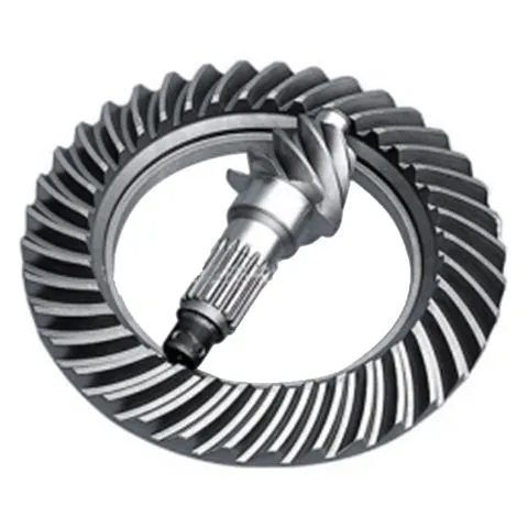
1. Why Does a Bevel Gear Lose Efficiency Even When the Tooth Geometry Is Correct?
The efficiency printed in a catalog is measured on a test rig under controlled conditions. The rig uses a new gear set, a specified oil, a controlled oil temperature, and a precise mounting alignment. In service, none of these conditions is exactly reproduced. The gear set wears, the oil ages, the oil temperature varies with the load and the ambient condition, and the mounting alignment changes with thermal expansion and foundation settling. Each of these changes adds a small loss, and the losses add up. In our factory, we measure the efficiency of every Bevel Gear set on a dynamometer at the rated load and at three oil temperatures. Saifu Vietnam Company Limited has been manufacturing bevel gear transmissions for over 15 years.
The drop from 96 to 89 percent in the example is typical for a drive that has run for three years without an oil change and without a mounting check. The loss is not a defect. It is a maintenance signal. The engineer can recover most of the loss by changing the oil, checking the backlash, and verifying the mounting alignment.
2. How Much Efficiency Is Lost to Sliding, Rolling, and Bearing Friction?
The total loss in a bevel gear transmission has four components. The first is the sliding loss at the tooth contact. The teeth roll and slide against each other, and the sliding generates friction. The sliding loss depends on the spiral angle, the gear ratio, and the surface finish. A higher spiral angle increases the contact ratio and reduces the sliding velocity, which reduces the loss. The second is the bearing friction. The bearings support the pinion and the gear, and their friction depends on the preload, the speed, and the oil viscosity. The third is the oil churning loss. The gear dips into the oil sump and churns the oil, and the churning loss depends on the oil level, the gear diameter, and the speed. The fourth is the seal friction, which is small but not negligible at high speed. The table below shows the distribution of these losses for a typical spiral bevel gear set.
| Loss component | At 1,500 RPM, 50% load | At 1,500 RPM, 100% load | At 3,000 RPM, 100% load |
| Tooth sliding loss | 1.5 – 2.0% | 2.0 – 2.8% | 2.5 – 3.5% |
| Bearing friction | 0.8 – 1.2% | 1.0 – 1.5% | 1.5 – 2.2% |
| Oil churning | 0.3 – 0.6% | 0.4 – 0.8% | 1.0 – 1.8% |
| Seal friction | 0.1 – 0.2% | 0.1 – 0.2% | 0.2 – 0.4% |
| Total loss | 2.7 – 4.0% | 3.5 – 5.3% | 5.2 – 7.9% |
The table shows that the loss increases with speed and load. The oil churning loss is the component that grows fastest with speed, because it is proportional to the cube of the speed. At 3,000 RPM, the churning loss can be three times the loss at 1,500 RPM. In our factory, we size the oil sump and the oil level to minimize the churning loss at the operating speed. We also recommend an oil cooler for high-speed applications to maintain the oil viscosity.
3. Why Does Lubrication Selection and Oil Level Change Measured Efficiency?
The oil viscosity determines the film thickness and the friction. A low viscosity oil reduces the churning loss and the bearing friction, but it may not maintain a sufficient film at high load. A high viscosity oil maintains the film but increases the churning loss and the bearing friction. The optimal viscosity is the one that maintains the film at the operating temperature with the minimum churning loss. The oil level also matters. An oil level that is too high increases the churning loss. An oil level that is too low starves the bearings and the tooth contact. The table below shows the effect of viscosity and oil level on the measured efficiency.
| Oil viscosity grade | Oil level | Measured efficiency at 1,500 RPM | Oil temperature rise |
| ISO VG 220 | Normal | 95.2% | 18°C |
| ISO VG 320 | Normal | 94.6% | 22°C |
| ISO VG 320 | High (+10 mm) | 93.1% | 28°C |
| ISO VG 320 | Low (-10 mm) | 94.9% | 26°C |
| ISO VG 460 | Normal | 93.8% | 25°C |
Transmission engineer's note: The oil level has a larger effect on efficiency than most engineers expect. Raising the oil level by 10 millimeters above the normal mark reduced the efficiency by 1.5 percentage points in the test. The oil level should be checked at the operating temperature, not at room temperature, because the oil expands when it is hot. In our factory, we mark the oil level on the sight glass for the operating temperature. Saifu Vietnam Company Limited provides the oil level specification and the recommended viscosity grade for each gearbox model.
4. How Do Mounting Accuracy and Backlash Setting Affect Efficiency in Service?
The mounting accuracy determines the contact pattern between the pinion and the gear. If the pinion is offset from the correct mounting distance, the contact pattern shifts toward the toe or the heel of the tooth. The shifted pattern increases the sliding velocity and the contact stress, which increases the loss. The backlash setting determines the clearance between the teeth. If the backlash is too small, the teeth bind and the temperature rises. If the backlash is too large, the teeth impact each other at each load reversal, which increases the noise and the loss. In our factory, we set the backlash according to the gear size and the operating temperature. We also check the contact pattern with marking compound before shipment. Saifu Vietnam Company Limited provides the mounting distance and the backlash range for each gear set.
We recommend that the installer verify the mounting distance and the backlash after the gearbox is installed on the foundation. The foundation settling and the thermal expansion of the housing can change the mounting distance by 0.05 to 0.10 millimeters, which is enough to shift the contact pattern. A contact pattern check after the first 500 hours of operation confirms that the alignment is still correct.
5. How Should Engineers Specify and Verify Bevel Gear Efficiency in Industrial Applications?
The specification should include six items. The first is the gear ratio and the spiral angle. The second is the accuracy grade according to the applicable standard. The third is the lubrication method and the oil viscosity grade. The fourth is the backlash range. The fifth is the mounting distance and the alignment tolerance. The sixth is the expected efficiency at the operating speed and load. The verification should include four tests. The first is the dynamometer efficiency test at the rated load and at the operating temperature. The second is the thermal equilibrium test, which measures the oil temperature rise at steady state. The third is the oil analysis, which measures the wear metals and the viscosity change. The fourth is the vibration and noise measurement. In our factory, we perform these tests on a sample basis for each production lot and provide the test report with the shipment. Saifu Vietnam Company Limited also offers an on-site efficiency measurement for installed gearboxes.
We recommend that the designer compare the expected efficiency with the measured efficiency after the first year of operation. A drop of more than 2 percentage points indicates that the oil, the backlash, or the alignment should be checked. A drop of more than 5 percentage points indicates that the gear set may need to be replaced.
Frequently Asked Questions About Bevel Gear Efficiency in Industrial Applications
Summary for Transmission Engineers and Maintenance Teams
Bevel Gear efficiency in industrial applications is affected by the sliding loss at the tooth contact, the bearing friction, the oil churning loss, the lubrication viscosity and oil level, the mounting accuracy, and the backlash setting. The catalog efficiency is measured under controlled conditions, and the in-service efficiency is lower because the conditions change with wear, temperature, and alignment. The engineer can recover most of the loss by maintaining the oil, checking the backlash, and verifying the mounting alignment. The specification should include the ratio, the accuracy grade, the lubrication, the backlash range, and the expected efficiency. The verification should include the dynamometer test, the thermal equilibrium test, the oil analysis, and the vibration measurement. Saifu Vietnam Company Limited has been manufacturing bevel gear transmissions for over 15 years and provides full efficiency specification and verification support for industrial applications.
