

Which Factors Influence Bevel Gear Manufacturing Accuracy and Consistency?
2026-11-13
A gearbox builder runs a batch of forty spiral bevel gear sets on the same machine, with the same drawing, and the same heat treatment cycle. The contact patterns on the first five sets are centered and acceptable. By the twentieth set, the pattern has moved toward the toe, and the tooth thickness has drifted toward the lower limit. The builder checks the machine and finds no fault. The problem is not one bad part. It is a loss of process consistency across the batch. This guide examines the factors that influence Bevel Gear manufacturing accuracy and consistency, and explains how our factory tracks each factor from blank preparation to final lapping. Saifu Vietnam Company Limited has been producing bevel gear sets for over 15 years.
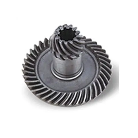
1. Why Do Contact Patterns Scatter Across a Batch of Bevel Gears?
Contact pattern scatter is usually a process capability issue, not a single-piece defect. The pattern position depends on the relative position of the pinion and the gear in the test fixture, and that position depends on the tooth geometry produced by the machine. If the blank runout, the workholding, the cutter wear, and the heat treatment distortion all vary within their individual tolerances, the combined variation can push the pattern outside the acceptance zone. In our factory, we treat the contact pattern as the final output of a chain of process variables, and we measure each variable before it can affect the pattern.
The first step is to separate the sources of variation. A batch that drifts gradually usually points to tool wear or thermal growth. A batch that scatters randomly usually points to blank runout or workholding. A batch that shifts after heat treatment usually points to distortion. Our production team keeps a batch record that lists the blank runout, the machine settings, the cutter life, and the heat treatment cycle for every lot. When the pattern moves, the team can trace the change to the variable that moved first.
2. How Do Gear Blank Geometry and Workholding Set the Accuracy Ceiling?
The gear blank is the foundation of the tooth geometry. If the blank has a high face runout or a high outside diameter runout, the machine will cut the teeth relative to a moving datum, and the tooth spacing and the tooth thickness will vary around the circumference. The workholding must also be rigid enough to resist the cutting force without deflection. A soft fixture or a worn chuck jaw allows the blank to move during cutting, and the resulting tooth geometry is inconsistent. Our factory inspects every blank before it is released to the gear cutting cell. The table below shows the blank and workholding parameters that most directly affect consistency.
| Parameter | Typical control limit | Effect on tooth geometry |
| Blank face runout | 0.02 mm or less | Tooth thickness variation around the circumference |
| Blank outside diameter runout | 0.03 mm or less | Tooth spacing error and pattern shift |
| Bore-to-face squareness | 0.01 mm or less | Lead error and contact pattern tilt |
| Workholding deflection under cut | 0.005 mm or less | Random scatter within the batch |
| Chuck jaw wear | 0.01 mm or less | Progressive drift across the batch |
Manufacturing engineer's note: The blank runout is the most common cause of random scatter in a batch. A blank that is within the drawing tolerance but at the upper limit will produce a pattern that is acceptable on one side and marginal on the other. In our factory, we hold the blank runout to half of the drawing tolerance for any gear set that will be lapped after heat treatment. Saifu reviews the blank drawing with the customer before production and agrees on the pre-machining control limits.
3. Why Do Machine Settings and Cutter Wear Shift Tooth Thickness and Spiral Angle?
The machine settings define the theoretical tooth geometry. The cutter diameter, the cutter pressure angle, the machine center distance, the swivel angle, and the cutter head radius all contribute to the tooth thickness and the spiral angle. A small error in the machine setting produces a consistent offset across the batch. A worn cutter produces a gradual drift from the first piece to the last. The difference between the two is important for troubleshooting. A consistent offset is corrected by adjusting the machine. A gradual drift is corrected by changing the cutter or by adjusting the cutter life limit. Our factory records the cutter life in number of pieces and in cutting hours. The cutter is replaced at a fixed life limit, not when the teeth start to fail. The table below shows the machine and cutter parameters that influence accuracy.
| Parameter | Typical control limit | Effect on tooth geometry |
| Machine center distance | plus or minus 0.02 mm | Tooth thickness and pattern depth |
| Swivel angle | plus or minus 0.02 degrees | Spiral angle and pattern position |
| Cutter head radius | plus or minus 0.01 mm | Tooth curvature and contact pattern length |
| Cutter life limit | Fixed by piece count or cutting hours | Gradual drift in tooth thickness |
| Thermal growth of machine | Warm-up cycle before first cut | First-piece offset and batch drift |
In our factory, the machine is warmed up for a fixed cycle before the first piece is cut, and the first piece is inspected before the batch continues. The cutter life is tracked in a tool log, and the cutter is changed at the defined limit. Saifu Vietnam Company Limited keeps the tool log and the first-piece inspection report with the batch record so that the customer can review the process history.
4. How Does Heat Treatment Distort the Geometry Before Final Lapping?
Heat treatment is the largest single source of dimensional change in a bevel gear set. The carburizing and quenching cycle introduces thermal stress and phase transformation stress, and the part distorts. The tooth thickness changes, the spiral angle changes, and the contact pattern moves. The distortion is not uniform, so it cannot be fully corrected by a single offset. Our factory controls the distortion by selecting the steel grade, by controlling the carburizing depth and the quenching temperature, and by using a press quench for thin sections. The parts are then lapped or ground to restore the contact pattern. The table below shows the typical distortion and the compensation method.
| Distortion type | Typical change after heat treatment | Compensation method |
| Tooth thickness change | 0.08 to 0.15 mm | Leave grinding stock and grind after heat treatment |
| Spiral angle change | 0.05 to 0.10 degrees | Lap or grind to correct the pattern |
| Face runout change | 0.03 to 0.08 mm | Press quench and straighten before finish |
| Contact pattern shift | Toward toe or heel by 2 to 5 mm | Lap the pattern back to center |
Heat treatment engineer's note: The distortion cannot be eliminated, but it can be predicted. In our factory, we run a distortion trial for each new gear design and each new heat treatment lot. The trial measures the tooth thickness and the pattern position before and after heat treatment, and the result is used to set the pre-heat-treatment stock allowance. Saifu Vietnam Company Limited keeps the distortion trial report with the process sheet so that the lapping operator knows how much material to remove.
5. How Should Buyers Verify Batch Consistency Before Accepting a Bevel Gear Lot?
The buyer should verify the batch consistency at three levels. The first is the dimensional level, where the tooth thickness, the spiral angle, and the runout are measured on a sample from the first, middle, and last part of the batch. The second is the pattern level, where the contact pattern is checked on a test fixture at the specified torque. The third is the functional level, where the gear set is run in a noise test stand and the sound pressure level is compared with the limit. Our factory performs all three checks on every lot and provides the report with the shipment. The buyer should also ask for the blank runout record, the cutter life log, and the heat treatment distortion trial report. These documents show whether the process was in control, not just whether the sample passed.
We recommend that the buyer define the sample size and the acceptance criteria in the purchase order. A sample of five pieces from a batch of fifty is usually sufficient for the dimensional check, but the pattern check should include the first and last pieces because they represent the extremes of cutter wear. If the last piece shows a pattern that is outside the acceptance zone, the batch should be reworked or sorted. Saifu Vietnam Company Limited can provide a pre-shipment inspection report in the customer's format on request.
Frequently Asked Questions About Manufacturing Accuracy and Consistency
Bevel Gear manufacturing accuracy and consistency are determined by the blank geometry, the workholding, the machine settings, the cutter wear, and the heat treatment distortion. Each factor has a measurable control limit, and each factor must be recorded in the batch record so that a pattern shift can be traced to its source. The buyer should verify the batch consistency with dimensional, pattern, and noise checks, and should request the process records that show the batch was in control. When these factors are managed together, the contact pattern stays centered across the batch and the gear set performs as designed.
