

Why Is Bevel Gear Ratio Important in Mechanical Transmission Systems?
2026-10-26
A machine designer is specifying a right-angle drive for a conveyor system. The motor runs at 1,450 RPM, but the conveyor drum must turn at 180 RPM. The input and output shafts must be at 90 degrees to each other. The designer selects a Bevel Gear pair with a ratio of 8:1. The ratio determines not only the output speed but also the output torque, the bearing loads, the noise level, and the expected service life of the entire transmission. A ratio that is too small will leave the conveyor underpowered. A ratio that is too large will make the drive oversized, inefficient, and noisy. This guide explains why the ratio is the single most consequential parameter in a bevel gear transmission system.
1. Why Does the Gear Ratio Determine the Torque and Speed Balance in a Transmission System?
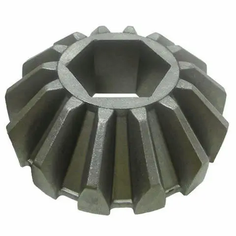
The ratio of a Bevel Gear pair is defined as the number of teeth on the driven gear divided by the number of teeth on the driving gear. If the driving gear has 20 teeth and the driven gear has 160 teeth, the ratio is 8:1. The output speed is the input speed divided by the ratio. The output torque is the input torque multiplied by the ratio, minus the efficiency loss. This is the fundamental trade-off of any transmission: speed and torque cannot both be increased. The ratio is the device that allocates the available power between the two. In our factory, we manufacture Bevel Gear sets with ratios from 1:1 to 10:1. Saifu Vietnam Company Limited has been producing bevel gear transmissions for over 15 years.
For the conveyor example, an input torque of 20 Nm at 1,450 RPM becomes an output torque of approximately 152 Nm at 180 RPM, assuming 95 percent efficiency. If the designer had chosen a 4:1 ratio, the output torque would be only 76 Nm, which would not be enough to start the loaded conveyor. If the designer had chosen a 16:1 ratio, the output speed would drop to 90 RPM, and the conveyor would run too slowly for the required throughput. The ratio must be matched to the load requirement, not selected by habit or by what is available in the catalog.
2. What Happens to Bearing Load and Efficiency When the Ratio Is Misselected?
When the ratio is too small, the output torque is insufficient. The motor draws more current to compensate, which increases the temperature rise and reduces the motor life. The gear teeth experience higher tangential forces, which accelerates pitting and wear. When the ratio is too large, the output speed is lower than required, and the system must be run at a higher input speed to compensate. The higher input speed increases the sliding velocity at the tooth contact, which raises the oil temperature and reduces the efficiency. The table below shows the effect of ratio selection on output parameters for a 15 kW drive.
| Ratio | Output speed at 1,450 RPM input | Output torque (Nm) | Efficiency range | Typical consequence |
| 3:1 | 483 RPM | 285 | 97 – 98% | Insufficient torque for heavy load |
| 5:1 | 290 RPM | 470 | 96 – 97% | Balanced for medium load |
| 8:1 | 181 RPM | 745 | 94 – 96% | Balanced for heavy load |
| 12:1 | 121 RPM | 1,100 | 92 – 94% | Output speed may be too low |
| 20:1 | 73 RPM | 1,800 | 88 – 91% | High sliding loss; heat and noise |
The efficiency drops as the ratio increases because the sliding velocity at the tooth contact increases. The sliding friction generates heat, which must be dissipated by the lubricant. In our factory, we test the efficiency of every Bevel Gear set on a dynamometer at the rated load. The test data is provided with each shipment so that the designer can verify the efficiency at the selected ratio.
3. How Does the Ratio Affect the Selection of Gear Type and Mounting Configuration?
The ratio determines which type of bevel gear is appropriate. Straight bevel gears are suitable for ratios up to 3:1 and low peripheral speeds. Spiral bevel gears are suitable for ratios up to 8:1 and higher speeds because the spiral angle provides smoother tooth engagement. Hypoid bevel gears are suitable for ratios up to 10:1 and provide a quieter operation because the pinion axis is offset from the gear axis. The table below shows the recommended gear type and mounting configuration for different ratio ranges.
| Ratio range | Recommended gear type | Typical mounting | Typical application |
| 1:1 – 3:1 | Straight bevel | Simple straddle mount | Hand tools, differentials |
| 3:1 – 6:1 | Spiral bevel | Straddle mount with preloaded bearings | Conveyors, mixers |
| 6:1 – 10:1 | Spiral or hypoid bevel | Overhung pinion with duplex bearings | Gearboxes, automotive axles |
| > 10:1 | Hypoid or two-stage | Overhung with heavy-duty bearing support | Heavy machinery, crushers |
Design engineer's note: The ratio also affects the axial thrust on the pinion and the gear. A spiral bevel gear generates an axial force that increases with the ratio and the spiral angle. The bearings must be selected to handle this thrust. In our factory, we provide the axial and radial load data for each Bevel Gear set so that the bearing selection can be verified. Saifu works with the customer's design team to confirm the mounting configuration before production.
4. Why Does the Ratio Influence Noise, Backlash, and Service Life?
The ratio affects the sliding velocity at the tooth contact, which is the primary source of noise and heat. A higher ratio means a higher sliding velocity, which produces more noise and more heat. The ratio also affects the backlash. The backlash is the clearance between the teeth when the gears are meshed. A higher ratio requires a larger backlash to accommodate the thermal expansion and the deflection under load. If the backlash is too small, the teeth will bind and wear rapidly. If the backlash is too large, the transmission will be noisy and will lose positioning accuracy. The table below shows the recommended backlash for different ratios and gear types.
| Ratio | Recommended backlash (mm) | Noise level (dB at 1 m) | Expected service life (hours) |
| 2:1 | 0.05 – 0.10 | 62 – 68 | 20,000 – 30,000 |
| 5:1 | 0.08 – 0.15 | 68 – 75 | 15,000 – 25,000 |
| 8:1 | 0.12 – 0.20 | 72 – 80 | 12,000 – 20,000 |
| 12:1 | 0.18 – 0.28 | 78 – 85 | 8,000 – 15,000 |
In our factory, we measure the backlash of every Bevel Gear set after assembly. The measurement is performed with a dial indicator at the pitch circle. The backlash must be within the range shown in the table for the specified ratio. We also perform a run-in test to verify the noise level and the contact pattern. Saifu Vietnam Company Limited provides a test report with each shipment that includes the backlash, the noise level, and the contact pattern photo.
5. How Should Engineers Verify the Ratio Before and After Installation?
Before installation, the engineer should verify the ratio by counting the teeth on both gears. The ratio is the number of teeth on the driven gear divided by the number of teeth on the driving gear. The engineer should also verify that the gears are marked with the correct ratio and that the marking matches the purchase order. After installation, the engineer should measure the actual speed ratio by running the system at a known input speed and measuring the output speed with a tachometer. The measured ratio should match the calculated ratio within 1 percent. A larger deviation indicates a marking error or a misassembly. In our factory, we mark every Bevel Gear with the ratio and the serial number. The marking is laser-etched on the gear face so that it remains visible after installation.
We also recommend that the engineer verify the contact pattern after the first loaded run. The contact pattern should be centered on the tooth face and should cover 60 to 70 percent of the tooth length. If the pattern is shifted toward the toe or the heel, the mounting distance is incorrect, and the ratio will not be realized as designed. Saifu Vietnam Company Limited provides a contact pattern guide with each gear set and offers on-site support for critical installations.
Frequently Asked Questions About Bevel Gear Ratio in Transmission Systems
Summary for Design Engineers and Maintenance Teams
The bevel gear ratio is the parameter that allocates the available power between speed and torque. It affects the output speed, the output torque, the bearing loads, the efficiency, the noise, the backlash, and the service life. A ratio that is too small leaves the load underpowered. A ratio that is too large makes the drive inefficient and noisy. The ratio also determines the appropriate gear type and mounting configuration. Before installation, the ratio should be verified by counting the teeth. After installation, the ratio should be verified by measuring the input and output speeds. By treating the ratio as a system-level design decision rather than a catalog selection, engineers can achieve a transmission that is efficient, quiet, and durable. Saifu Vietnam Company Limited has been producing bevel gear transmissions for over 15 years and provides full ratio selection and verification support for our customers.
