

Why Is My Pneumatic Micro-Flow Diaphragm Actuator Experiencing Hysteresis and Deadband Issues
2026-06-23
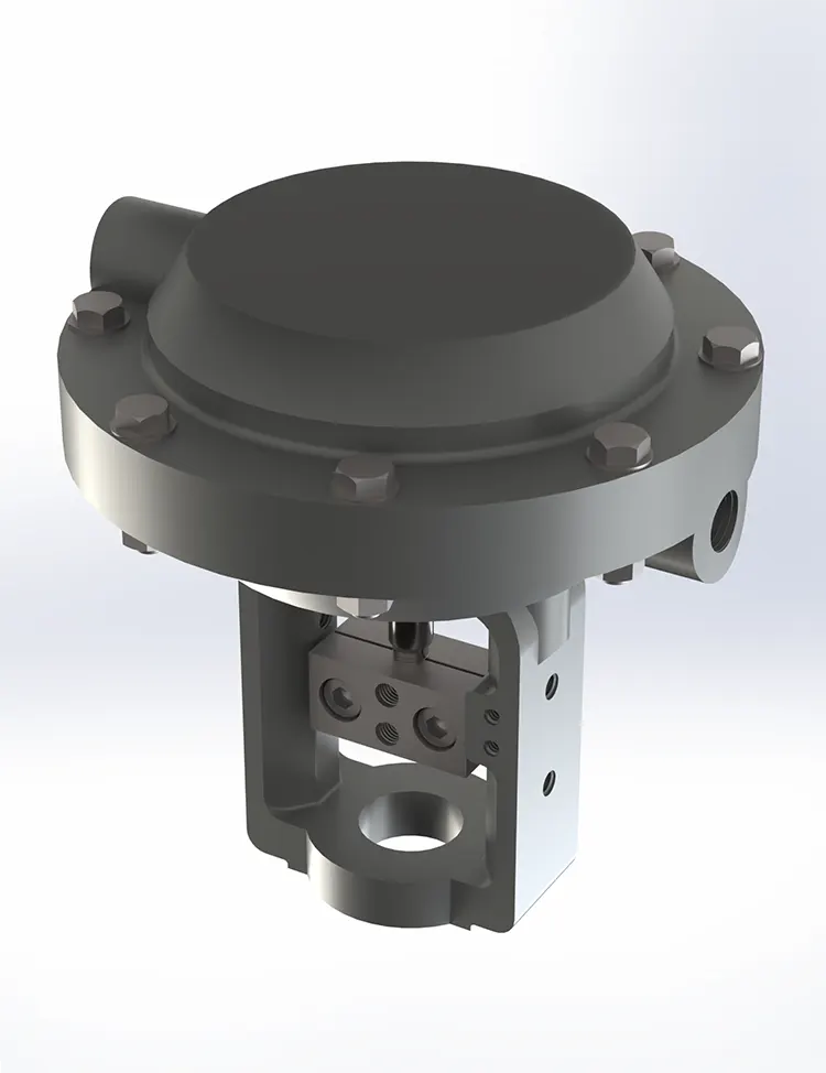
If you operate a Pneumatic Micro-Flow Diaphragm Actuator in precision fluid or gas control, you have likely encountered two frustrating performance killers: hysteresis and deadband. These nonlinearities translate directly into lost accuracy, inconsistent dosing, and rejected batches. At LOZOSE, we have diagnosed hundreds of these cases across pharmaceutical filling, analytical instrumentation, and semiconductor gas panels. This guide walks you through the root causes, quantifiable diagnostics, and actionable fixes—so your Pneumatic Micro-Flow Diaphragm Actuator returns to its specified ±0.5% positional accuracy.
Hysteresis vs. Deadband – Quick Distinction
| Term | Definition | Typical Acceptable Limit |
|---|---|---|
| Hysteresis | Maximum difference in output position for the same input signal, approached from opposite directions (increasing vs. decreasing pressure). | < 0.8% of full span |
| Deadband | Range of input signal change that produces no observable output movement. | < 0.5% of full span |
Both errors compound in a Pneumatic Micro-Flow Diaphragm Actuator because the flexible diaphragm, spring preload, and pilot valve spool interact mechanically and pneumatically.
5 Root Causes – Ranked by Frequency (LOZOSE Field Data)
| Cause | Contribution Rate | Diagnostic Sign |
|---|---|---|
| Stiction in pilot valve spool | 38% | Erratic step response, stick-slip motion |
| Diaphragm fatigue or permanent set | 27% | Increasing hysteresis with temperature cycles |
| Incorrect bench-set spring preload | 15% | Asymmetric deadband (worse on one direction) |
| Supply pressure droop | 12% | Deadband expands at high flow demands |
| Electronic I/P converter drift | 8% | Hysteresis follows warm-up drift pattern |
Step-by-Step Diagnostic Workflow
-
Record a full up-down cycle – Apply 3–15 psi (or 4–20 mA) in 5% increments, then decrement back. Plot input vs. output stroke.
-
Measure hysteresis – At 50% stroke, read output on increasing vs. decreasing curve. Difference = hysteresis value.
-
Measure deadband – From zero, increase signal slowly. Record the first signal change that moves the stem. That value is your deadband.
-
Compare against factory certificate – Your LOZOSE Pneumatic Micro-Flow Diaphragm Actuator ships with a signed test curve. A >30% deviation from that curve signals mechanical degradation.
Practical Fixes – What Actually Works
-
For pilot valve stiction: Remove, ultrasonically clean in isopropanol, and relubricate with instrument-grade grease (e.g., Krytox). Never use hydrocarbon-based oils—they attack the diaphragm elastomer.
-
For diaphragm set: Replace the diaphragm assembly. LOZOSE offers pre-aged diaphragms that reduce break-in hysteresis by 60% from the first cycle.
-
For spring preload: Re-bench-set using a dead-weight tester. Adjust the compression nut until the Pneumatic Micro-Flow Diaphragm Actuator begins moving at 0.3 psi above zero (factory standard).
-
For supply pressure: Install a dedicated precision pressure regulator within 1 ft of the actuator. Droop must stay < 0.5 psi at maximum flow.
-
For I/P drift: Perform a 5-point auto-calibration with a certified reference pressure gauge.
When to Replace vs. Repair
| Condition | Recommended Action |
|---|---|
| Hysteresis > 2.5% after cleaning and recalibration | Replace – diaphragm or spool wear is irreversible |
| Deadband > 1.5% but hysteresis < 1.0% | Repair – adjust preload and replace pilot spring |
| Both errors appear suddenly after a pressure spike | Inspect – possible stem bending or seat damage |
| Gradual degradation over 18+ months | Preventive replacement – schedule with LOZOSE service kit |
FAQ – Pneumatic Micro-Flow Diaphragm Actuator Common Questions
Q: Can a Pneumatic Micro-Flow Diaphragm Actuator develop hysteresis from upstream filter blockage?
A: Yes, indirectly. A clogged inlet filter reduces the available pilot pressure during high-flow demand. When the actuator attempts to follow a rising setpoint, the restricted flow causes a temporary pressure lag. On the descending stroke, the same restriction does not affect exhaust equally. This asymmetric response produces a loop-shaped hysteresis curve that can exceed 1.5%. Always replace the 5-micron sintered filter every 6 months or whenever supply pressure (measured dynamically) drops more than 2 psi below the regulated setpoint.
Q: What is the correct method to measure deadband in a Pneumatic Micro-Flow Diaphragm Actuator without a laser displacement sensor?
A: Use a mechanical dial indicator with 0.001-inch resolution mounted axially on the stem. Zero the indicator at full close. Apply your control signal in 0.05-psi increments from zero using a calibrated test pressure regulator. Record each pressure point and the corresponding indicator reading. Deadband is the first pressure increment that produces a sustained movement of at least 0.002 inches (or your application’s minimum resolution). Repeat three times and average. For higher confidence, perform the same test at 25%, 50%, and 75% of full stroke—deadband often varies with position due to non-linear spring rates.
Q: How does operating temperature affect hysteresis in a Pneumatic Micro-Flow Diaphragm Actuator, and can I compensate digitally?
A: Temperature affects three components: the diaphragm elastomer modulus (stiffens in cold, softens in heat), the pilot valve solenoid resistance (shifts I/P output), and the spring steel rate (changes ~0.02% per °C). In practice, hysteresis can double from 0.8% at 20°C to 1.6% at 50°C. Digital compensation is possible but requires a built-in temperature sensor and a customized lookup table in your PLC. LOZOSE offers an optional smart positioner with real-time temperature correction that reduces thermal hysteresis to below 0.4% across a 0–60°C range. Without such compensation, you should re-characterize the actuator at your actual process temperature every quarter.
Final Recommendation
Do not chase hysteresis and deadband with PID tuning alone—that masks the root mechanical issue. Start with the diagnostic workflow above. If you need factory-grade test data, replacement diaphragms, or a pre-configured LOZOSE Pneumatic Micro-Flow Diaphragm Actuator with verified <0.5% combined error, our engineering team is ready.
Contact us today with your actuator model, operating pressure range, and a recent stroke curve. We will respond within 4 business hours with a root-cause analysis template and a tailored corrective action plan.
